
Network Lab 3 – Advanced Security and Redundancy
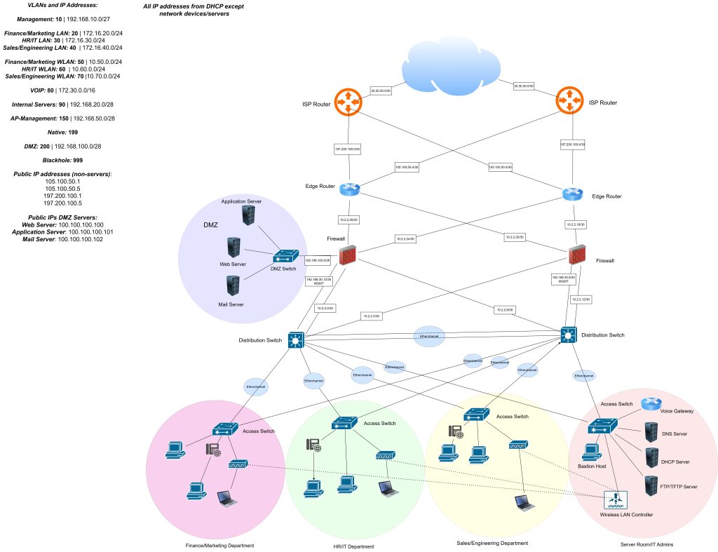
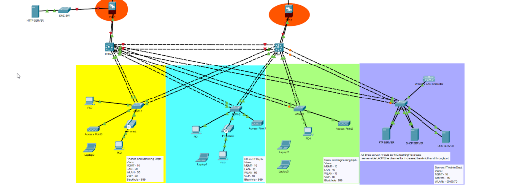
Implementing a collapsed-core enterprise network with emphasis on security, redundancy, and high availability. Key technologies include HSRP, EtherChannel, Rapid-PVST+, OSPF, firewalls, a DMZ zone, wireless controller integration, wireless connectivity and comprehensive Layer 2 security.
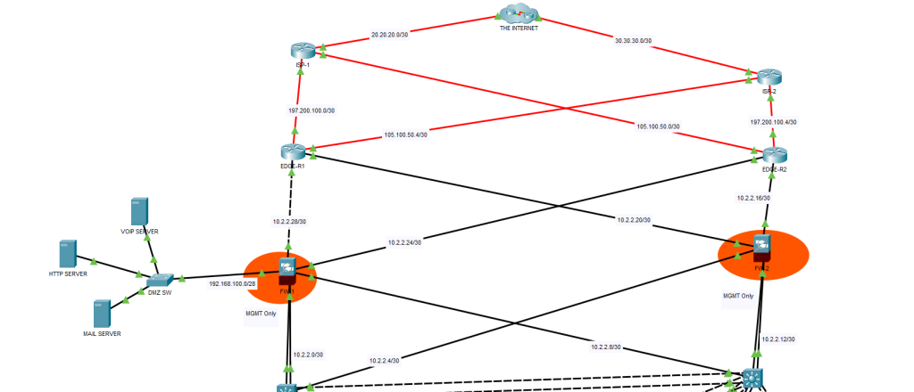
Logical network topology diagram:
Device Hardening
User Authentication & Access Control:
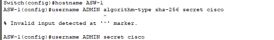
- Use algorithm-type command in a real environment instead of just secret.
- Username and hostname configured.
- Hostname should have a specific naming convention to improve device identification.
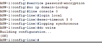
- All passwords (current and future) encrypted.
- Device no longer conducts a DNS query when there is a typo – saves time.
- Console line configured and hardened with a timeout after 3 minutes of inactivity.
- Authentication by local user account.
SSH Configuration:
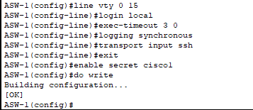
- VTY lines and privileged EXEC mode configured and hardened. Limited remote access to SSH – no Telnet.
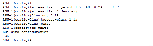
- Access Control List created to restrict access to SSH to only 8 management PCs!
- Reduces blast area if the management network is somehow compromised and provides greater segmentation.
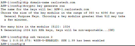
- All the parameters needed to configure SSH version 2 completed.
- Only SSH version 2 allowed.

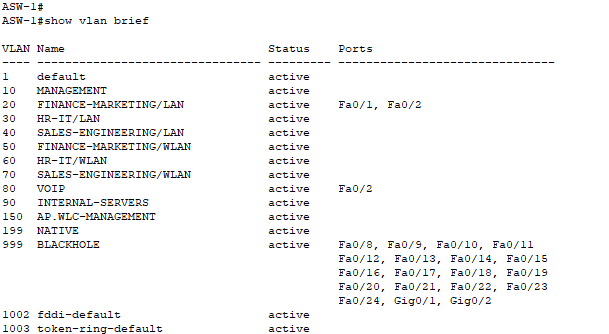
- All switches have their VLANs configured and named.
- Only added VLANs immediately connected to the access switches.
- Distribution switches need ALL existing VLANs in the network.
- Blackhole VLAN is for the ports we will soon shutdown on the access switches.
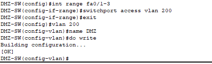
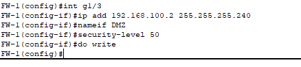
- DMZ-Switch VLAN configured. DMZ server room would have state of the art physical security, but we further improved security by taking off the servers from VLAN1 (default) to VLAN200.
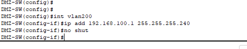
- DMZ switch SVI created in VLAN200 so our management VLAN does not extend into the DMZ.
- Creating ACL on switch itself that permits SSH only from the authorized management PCs in VLAN10.
- Creating ACL on firewall to allow only VLAN10 management PCs to reach the switch management IP address – enforcing least privilege and defense in depth.
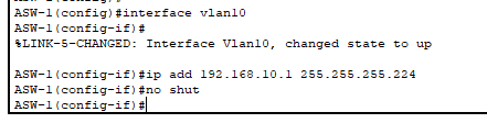
- SVI configured in VLAN 10 on access switches for remote access (SSH) management capabilities.
- It is a /27 mask so we have 30 usable hosts/addresses!
- Our management PCs live in this network as well.
- Note: At least one port on the switch must have VLAN 10 enabled for the SVI to be up. This will be done with the trunk Etherchannels we’ll configure later.
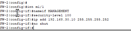
- Dedicated management port so no production traffic is shared in this link.
- Security levels define how much you trust the network facing the port. By default, traffic is allowed to flow from higher to lower levels (LAN -> DMZ or WAN).
- LAN will have level 100 security, DMZ level 50, and WAN level 0.
- Traffic is blocked by default if it flows from a lower to higher level (WAN -> DMZ/LAN or DMZ -> LAN).
- Need to at least configure ACLs to explicitly allow traffic when the above occurs (there’s other methods besides ACLs to accomplish this).
- If traffic originated from a higher level security zone, stateful inspection tracks these sessions and allows return traffic automatically without requiring explicit ACLs.
- Other methods: firewall rules which are more granular in nature, Application Inspection, etc.
- Note: As we only have one management interface per firewall, we do not have remote management redundancy if the distribution switch directly connected to a firewall fails. We do however maintain production redundancy where all data traffic continues flowing.
- Mitigation options:
- Console access backup: If either distribution switch fails, console access to the affected firewall remains available as an emergency management method.
- Repurpose a data port: We can repurpose a data port on the firewall to become the redundant management link and ensure no production traffic enters here. Must apply a strict ACL here however.

- Distribution Switch-2 port connected to the management port of FW2.
- Will configure ACLs to limit which management PCs can SSH to the firewall.
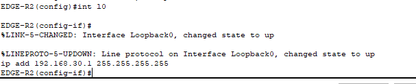
- For the Edge Routers, we will configure loopback interfaces.
- Why loopback? These are logical interfaces that remain administratively ‘up‘ regardless of physical ports status; however it is only reachable if at least one physical port has an active path to the network.
- We configure them with the /32 mask.
The type of management we will be using in this network is in-band management. For true segmentation (out-of-band management), we would need an entirely different physical infrastructure that enables our management network to still be online even if the production network goes down.
Remote management IP addresses for the distribution switches will be configured later when we set up HSRP, as we’re using SVIs on these switches as the default gateways for our hosts in each VLAN.
Access Switch Port Configuration
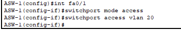
- For the ports connected to just PCs, this would be the configuration. Configuring ASW-1 (Finance Department) – using VLAN20. Access ports carry only one VLAN.

- For the ports connected to an IP phone and a PC, this would be the configuration.
- The port is still an access port but the switch knows there’s an IP phone as well.
- VoIP traffic should receive better treatment than regular data, but switches don’t trust QoS markings coming from access ports, which is why the ‘mls qos trust cos’ command is needed.
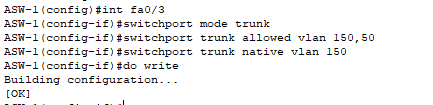
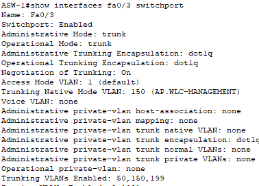
- Port that connects to our Wireless Access Point.
- This configuration uses two separate VLANs for wireless for:
VLAN 150: Management VLAN for APs and their CAPWAP tunnel to the WLC.
VLAN 50: Data VLAN for wireless client traffic. - Note: You typically do not configure the native VLAN to match the WLC’s management VLAN because then the AP port will be sending out untagged frames while the WLC is expecting frames tagged with the management VLAN. This will cause connectivity issues.
- This was configured as is because of a Packet Tracer bug where the WLC loses connectivity if you change its management VLAN from the default untagged configuration.
- If your APs broadcast multiple SSIDs mapped to different VLANs, add those VLANs to the trunk’s allowed list to support the additional client traffic.
- Now for our 4th access switch (connected to the servers):
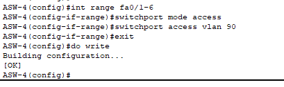
- All three of our servers are on the same VLAN, which is 90.
- Realistically, servers typically use NIC teaming (also called bonding or link aggregation) to combine multiple physical NICs into a single logical interface – increasing bandwidth and throughput. The server-side NIC team would connect to an LACP EtherChannel on the switch, with both sides actively negotiating the link aggregation using the Link Aggregation Control Protocol.
- Due to Packet Tracer’s limitations on server-side NIC teaming and LACP configuration on server devices, each server has two separate access port connections mimicking a single logical Etherchannel link.
For the port connected to the Wireless LAN Controller:
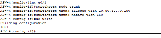
- Configured as a trunk to carry multiple VLANs such as:
- AP management traffic (VLAN150).
- Wireless data traffic from multiple WLANs which are mapped to different VLANs.
- Management PC traffic (VLAN10).
- Only allowed the necessary VLANs for security best practice.
For the port connected connected to our Voice Gateway/Call Manager:
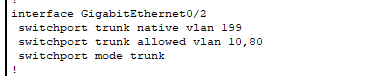
- Configured as a trunk to allow VLAN10 management traffic as well besides the VoIP VLAN.
- Configured native VLAN to an unused VLAN for improved security.
- Connected port on the actual Voice Gateway must be router on a stick implementation – configured later when configuring VoIP.
This is how this portion of the network is looking currently.
Layer 2 Security
Time to configure Layer 2 security on our Access switches:
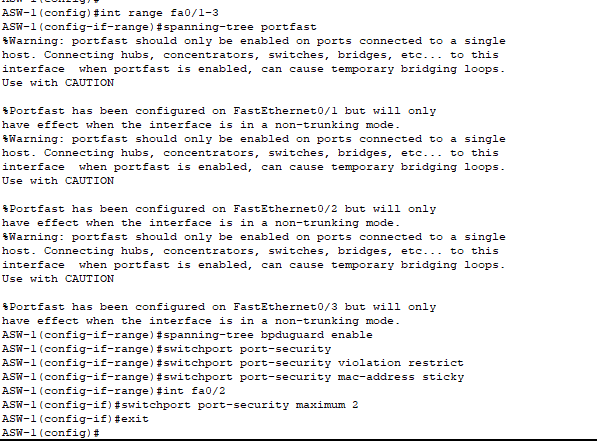
- PortFast is enabled on all access ports, including the trunk link to the AP, to transition interfaces immediately to the forwarding state without waiting for STP convergence.
- Should only be enabled on ports connected to end devices and never to ports connected to other switches.
- BPDU Guard is enabled on all PortFast ports to automatically disable the interface if a BPDU is received. This prevents unauthorized switches from being connected to access ports and potentially disrupting the network.
- Port Security limits the number of devices allowed per port based on learned MAC addresses.
- Standard access ports, including the ones connected to WAPs: maximum 1 address.
- VoIP ports need to learn 2 MAC addresses (for the PC and IP phone).
- Learning mode: Sticky – first MAC address(es) learned are saved to the running configuration.
- Violation action: Restrict – unauthorized MAC addresses have their frames dropped and a log is generated.

- Both DHCP snooping and Dynamic ARP Inspection (DAI) are enabled for security. All uplink interfaces connecting to the distribution switches are configured as trusted ports, allowing legitimate DHCP and ARP traffic from them.
- Note: In production environments, DHCP snooping and DAI trust settings should be configured on the port-channel interface itself, not on the individual member ports that make up the EtherChannel.
- Due to Packet Tracer’s limitations, we configured trust on the individual physical uplink interfaces. However, in real deployments, you must configure trust on the port-channel interface to ensure proper operation and avoid potential connectivity issues.
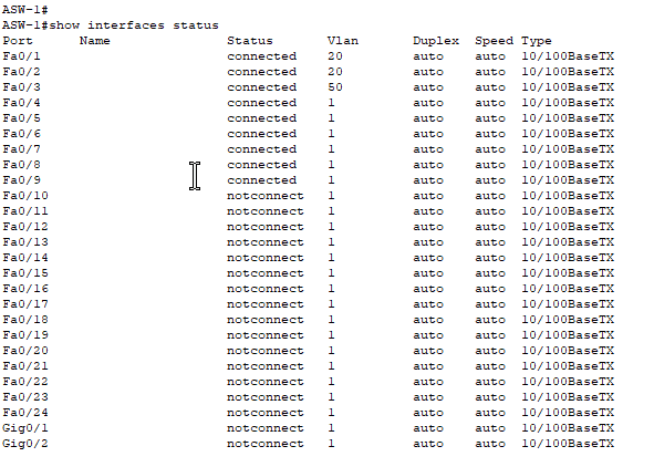
- Note: it shows interface Fa0/2 as only being in VLAN 20.
- Here, you can see the interface Fa0/2 is also in VLAN80.
- This command is only for access VLAN ports.
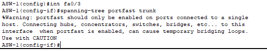
- Configuration for the AP trunk link!
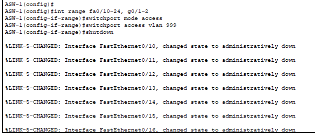
- We placed all unused ports into the blackhole VLAN (VLAN999) and then disabled them for defense in depth.
- Utilized a blackhole VLAN so if somehow a bad actor is able to gain access to the switch and enable a port, they would be in a completely isolated network.
- This is configured only on the access switches connected to end hosts and where less-trusted devices connect.
- Our infrastructure switches (including those connected to the internal servers and the DMZ) typically don’t require this defense tactic because:
- These switches are located in extremely secured areas (locked server rooms, data centers) where physical access is strictly controlled and monitored.
- All ports on these switches serve specific infrastructure purposes.
Configuring Etherchannel
Access to Distribution Switches

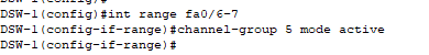
- Configured a LACP (command = active) Etherchannel with Distribution-SW 1 from two different interfaces on ASW-1.
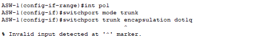
- Configured the Etherchannel link as a trunk link and tried to specify to use protocol 802.1Q for VLAN tagging. Switch did not support this command because it only supports 802.1Q – ISL deprecated.
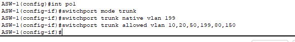
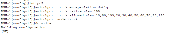
- Trunk link configured with security in mind and native VLAN specified.
- Configure native VLAN to an unused VLAN for maximum security.
- Only allow the VLANs directly connected to the switches and for management.
Distribution to Access Switches

- Highlighting the topic before, the distribution switch required me to specify if I am using 802.1Q.
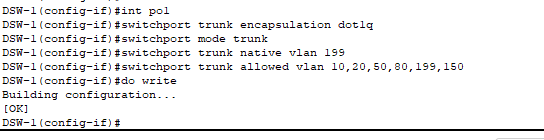
- Complete configuration for each Etherchannel link to the access switches from the Distribution switches.
- Note: Only allow the same VLANs that are located on the access switch for security.

- Remember: confirm that the native VLAN is the same on both ends of the trunk link. Received this error before I could configure the other side of the link.
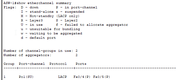
- Use ‘
show etherchannel summary‘ after each EtherChannel configuration to verify:- Port status showing “P” which indicates that the port is bundled in the port-channel.
- Flags showing “SU” (Layer 2) or “RU” (Layer 3).
- All member ports are listed under the correct port-channel.
- One misconfigured parameter (speed, duplex, VLAN, mode) on any member interface will prevent the bundle from forming.
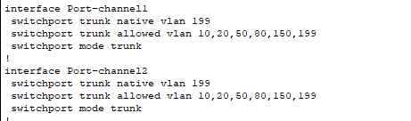
- With “show running-config” you can obtain trunk configurations for the Etherchannel links!
Distribution to Distribution Switch
EtherChannels can be configured as either Layer 2 (trunk) or Layer 3 (routed) links.
- However in our topology, it has to be a Layer 2 trunk due to the fact that:
- VLANs need to span both distribution switches for HSRP to function.
- SVIs on both switches provide redundant default gateways for each VLAN.
- Layer 2 connectivity ensures seamless failover between the two distribution switches.
- VLANs must bridge across this link to maintain the same broadcast domain on both sides.
- Similar configurations as to when we configured Etherchannel links between our access and distribution switches with the only difference being that we are allowing all VLANs that are currently utilized in our entire network.
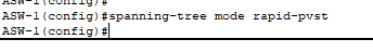
Now, all of our links have increased throughput and bandwidth! To maximize our redundant topology we’ll need to configure Rapid Per-VLAN Spanning Tree Plus. Note: This is Cisco proprietary – in a multi-vendor environment, you’d use Multiple Spanning Tree Protocol (MSTP).
- Rapid Per-VLAN Spanning Tree+ is a protocol used to block Layer 2 redundant links to avoid broadcast storms, loops and MAC table instability.
- Using Rapid-PVST+ instead of PVST because it reduces the convergence time from 50 seconds in traditional STP to 1-6 seconds whenever the topology changes.
- Using Per-VLAN+ because it runs a separate spanning tree instance for each VLAN, enabling per-VLAN load balancing.
- Without Per-VLAN instances, an entire Etherchannel trunk on each switch would be blocked by STP due to it being redundant.
Configuring Rapid-PVST+

- From our ‘show running-config’ output, we see that the switch is currently running regular PVST.
- Rapid PVST+ load balancing is achieved by designating different root bridges for each VLAN. Each VLAN uses the path toward its designated root bridge as their primary forwarding path, which distributes traffic across both EtherChannel uplinks and ensuring no entire link is blocked by STP.
- Configuration:
- Distribution Switch 1 will be our root bridge for VLANs 10, 20, 30, 40, 150 and 90.
- Distribution Switch 2 will be our root bridge for VLANs 50, 60, 70, 80 and 199.
- Configuration:
Note: The Rapid PVST+ root bridge configuration mirrors our upcoming HSRP design for consistency and optimal traffic flow:
- Primary root bridge = HSRP active router (primary default gateway).
- Secondary root bridge = HSRP standby router (backup default gateway).
- This ensures that Layer 2 forwarding paths (STP) match Layer 3 forwarding paths (HSRP). Traffic flows through the same path preventing suboptimal routing.
- This is the output for “show spanning-tree” on Distribution Switch 1 – the one we actually want to be the root bridge for in VLAN 10.
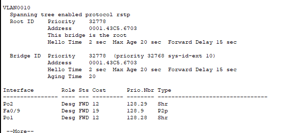
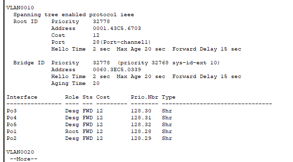
This is the output for Access Switch-1. This is what we can ascertain from these screenshots:
- ASW-1 is the root bridge for VLAN 10.
- You can confirm this because the Root ID “address” (MAC) is the same as the Bridge ID (local switch) in the second screenshot.
- You can also see all of the ports on ASW-1 are “designated” which signifies that they are all forwarding (due to being the root bridge). DSW-1 has a root port (which also forwards) but not all ports are labeled as designated. Only root bridges have all ports designated.
- With all of the switches using the default priority of 32778 for VLAN10, the root bridge election used MAC address as the tiebreaker. ASW-1 became the root bridge due to having the lowest MAC address
- You can configure the priority value to break the tie so the switches do not have to rely on using MAC addresses, which is what we’ll use to configure our root bridges for each VLAN.

- DSW-1 is now the root bridge in the VLANs we configured as “root primary” as well as being the secondary root bridge for all other VLANs.
- If DSW-2 fails, DSW-1 will automatically become the root bridge for those VLANs configured as “root secondary”.

- This is the command output on ASW-1, the former root bridge.
- You can see the Root ID priority changed to a lower number to ensure DSW-1 becomes root. The MAC of the Root ID changed to DSW-1’s MAC address.
- ASW-1 now has a Root port.
Configuring IP Addresses
- Here’s how we’ve configured IP addresses on the links connecting to the Internet:
- From the Distribution switches to the inside ports of the Edge routers, we’re using private IP addresses.
- On the outside facing ports of the Edge routers (towards our ISP), we’re using public IP addresses assigned by our ISP.
- These are the IP addresses that hosts on the Internet see as our source IP.
- We were only allocated 4 public IPs from our ISP.
- The Edge routers will perform PAT for our internal network to allow hundreds or thousands of internal devices to share these 4 public IP addresses.
- Our routers will not perform PAT for our DMZ hosts.

- Configurations for the Distribution switches to the firewalls (data traffic).
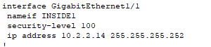
- Configurations for the firewalls to the Distribution switches (data traffic).
- Security-level is 100 because this port connects downstream to our trusted private network.
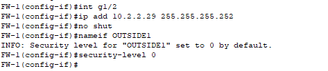
- Configurations from the firewall to the edge router.
- Security-level is 0 because we do not trust the Internet/WAN side whatsoever, zero trust.
- The command might seem redundant (since 0 is the default for interfaces named ‘outside’) but it doesn’t hurt to explicitly confirm the security level is set to 0!
- Configuration for the firewall to the DMZ.
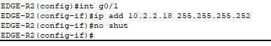
- Configurations for the edge routers to the firewalls.
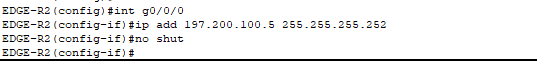
- Configurations for the edge routers to ISP routers.
- These IP addresses on our ISP-facing interfaces will be used as the translated addresses for PAT from our internal private networks. They are:
- 105.100.50.5
- 105.100.50.1
- 197.200.100.5
- 197.200.100.1
- These IP addresses on our ISP-facing interfaces will be used as the translated addresses for PAT from our internal private networks. They are:
Static IPs
All of our internal servers, WLC and DMZ servers will have their own static IPs – will not be using DHCP.
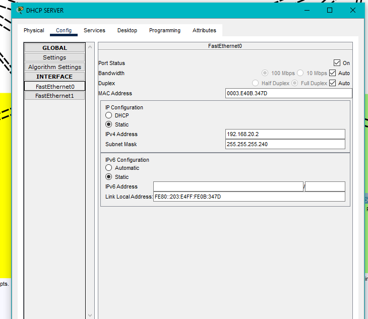
- DHCP server static IP.

- Static IP configuration for our WLC.
Configuring Redundant VLAN Gateways – HSRP

- We are mirroring our HSRP configuration the same way we configured R-PVST+. If DSW-1 was the root bridge for VLAN20, it would be the active default gateway for VLAN20. DSW-2 would be the standby gateway.
- The IP address “172.16.20.2” is the address we could use to SSH in and manage the switch remotely.
- The address “172.16.20.1” is the actual default gateway for all hosts in VLAN20 – both DSWs will use this same virtual IP.
- Increased priority to 120 to ensure this switch is the active gateway, used preempt in case if it fails and comes back, it takes over as the active gateway again (DSW-2 would take over if DSW-1 fails).
- Same configurations for DSW-2 except modeled after how R-PVST+ was configured!
- No SVI created for native VLAN 199 because there are no actual hosts in this VLAN.
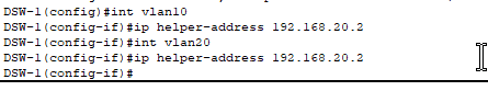
- Configured ‘helper-address’ on each SVI so that when hosts in each VLAN send out their DHCP broadcast message (DHCPDISCOVER), the DSW can forward these messages to our DHCP server as unicast packets, allowing the hosts to successfully obtain IP addresses when the DHCP server is located in a different VLAN!

Configuring the DHCP server
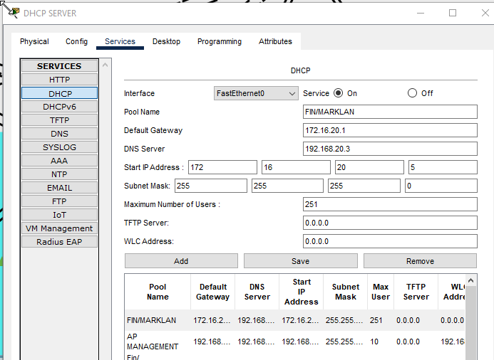
- DHCP pool for VLAN20.
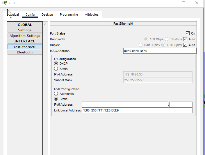
- Our PC connected to ASW-1 in VLAN 20 (LAN) received their DHCP IP address!
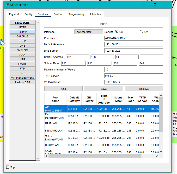
DHCP Scope for our Wireless Access Points:
- Ensuring our WAPs get their IP addresses from this scope. This is not the scope for wireless clients sending data traffic.
- Default gateway is the SVI we configured on Distribution switches.
- The WLC IP address configured here therefore our DHCP server will send Option 43 to our APs so they may form their CAPWAP tunnels to the WLC.
- Lightweight APs (which is what we are using) need to form CAPWAP tunnels to a WLC to pass management traffic.
- Additionally, as our APs are using local mode and not FlexConnect, they also have to forward all data traffic to the WLC through the CAPWAP tunnel before they reach the wired network.
- Can configure our APs within WLC to use FlexConnect instead after CAPWAP tunnel is formed.
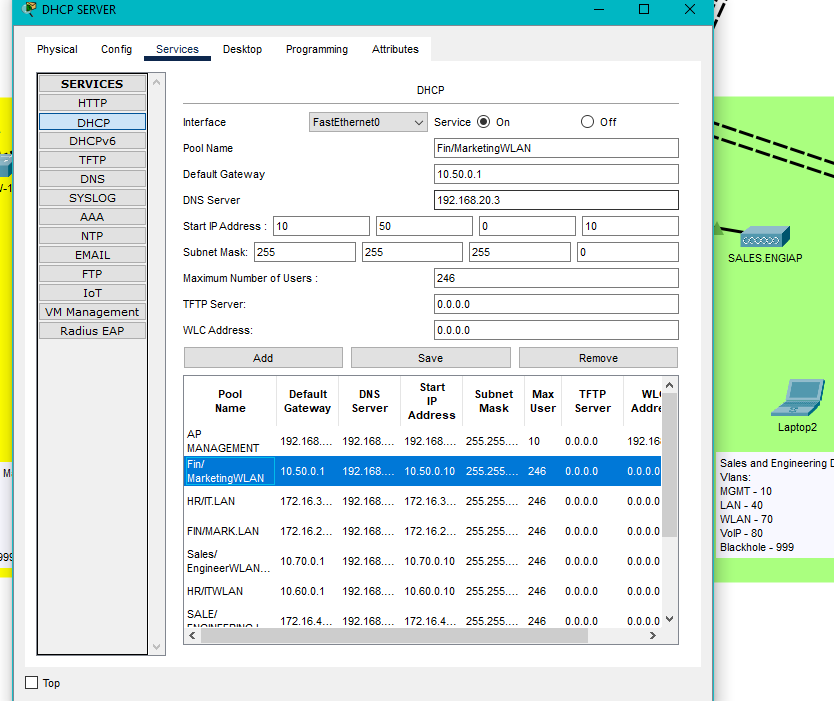
- DHCP pool for one of the WLANs.
- This is for wireless clients.
- No WLC address configured.
Configuring OSPF and Static Routes
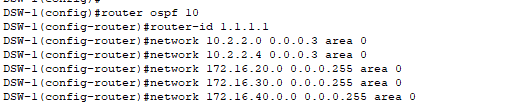
OSPF Configuration on Distribution Switch:
- OSPF process ID (10) does not have to be unique across all devices – it’s only locally significant.
- Router ID MUST be unique per device!
- Advertising all of our directly connected networks on each network device:
- For the Distribution Switches:
- Links connected to the firewalls (Data only – not management!).
- Internal servers VLAN.
- All LAN VLANs (user networks).
- All WLAN VLANs (wireless networks).
- Not advertising VoIP VLAN because all of VoIP traffic is local, no external calls and no call manager in this project.
- Management VLAN should stay isolated and not be advertised to routing protocols for security reasons.
- OSPF uses wildcard subnet masks which is the inverse of subnet masks!
- The areas configured on the connecting interface between OSPF neighbors MUST match.
- Therefore, if DSW1’s interface to FW1 is in Area 0, then FW1’s interface back to DSW1 must also be in Area 0.
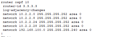
- Firewall operating systems do not require the mask to be a wildcard!
- These are the 5 direct links attached to the firewall (one being the DMZ).
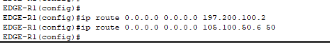
- On the edge routers I created a static default route (administrative distance of 1 by default) pointing to the ISP’s router interface as the next hop for all Internet traffic. For the redundant link, I created a floating static route to the backup ISP link with a higher AD (50). If the primary link fails, traffic immediately starts flowing to the redundant link ensuring uninterrupted connectivity.
- Created the static route pointing to our DMZ web server with the firewall interface as the next-hop.
- Route uses the web server’s public IP address as the destination because that’s the IP address that will be present in packets arriving from the Internet. When external users connect to our web server, they use the public IP – the Edge Router needs to know how to route those packets to the firewall for NAT translation.
- Remember our edge routers are not performing PAT for our DMZ hosts.
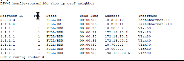
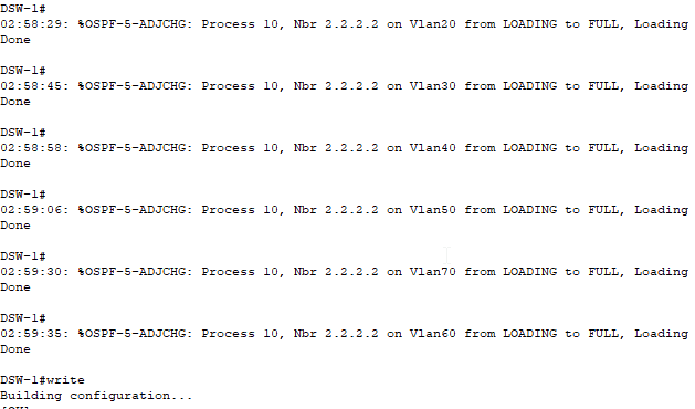
- We can see what OSPF adjacencies were established using the command ‘show ip ospf neighbor’.
- On our DSW-2, we have neighbors now with our DSW1 and two firewalls.

- Don’t forget to advertise the default route to the Internet on the edge routers using ‘default-information originate’ command in OSPF.
- Without this command, the Edge Routers know how to reach the Internet due to their static default routes to the ISP, but no one else in the network knows to use the Edge Routers for Internet-bound traffic.
- This command explicitly injects a default route into OSPF.
- Note: Some enterprises may decide not to create an OSPF adjacency between the firewall and edge routers for security purposes.
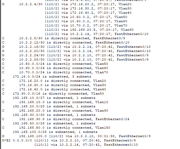
- Look at some of the routes our DSW-2 learned through OSPF!
- The default routes to the edge router are here with the code “O*E2” – it learned both pathways to the Internet.
- It also learned the path to the DMZ through our FW1.
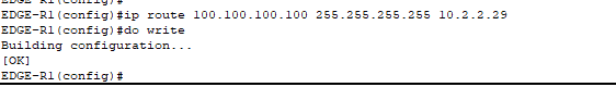
Last thing we need to configure are routes to our edge router’s loopback interfaces for remote management! We do not want to advertise these routes through OSPF for security purposes.
Wireless Configuration
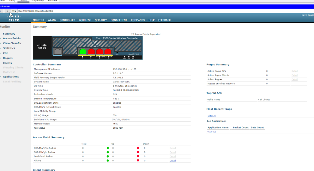
- Due to a Packet Tracer quirk, we’re unable to configure our WLC through its console port so we’re going to have to resort to remotely configuring the WLC using the HTTP(s) GUI!
- Realistically, you must connect first with the console port to configure a management IP address to then be able to configure using the HTTPs GUI.
- We will be utilizing a bastion host to remotely configure the WLC. A hardened bastion host provides secure administrative access, minimizing the attack surface by centralizing management connections through a single, secured entry point. This host will also be remotely managing the rest of our network devices.
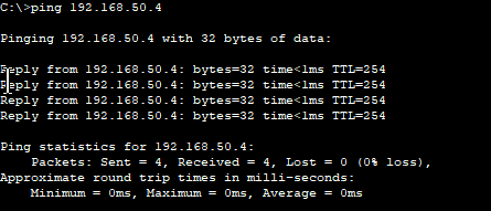
- Able to ping the WLC from the bastion host!
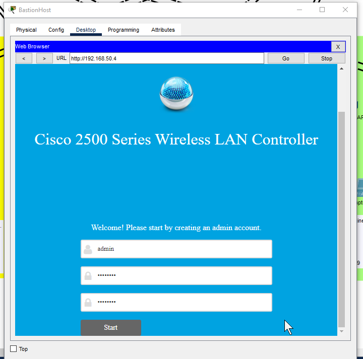
- HTTP into the WLC and configuring it. Ideally would use HTTPs on port 443 as it is more secure but unable to due to Packet Tracer limitation.
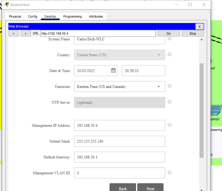
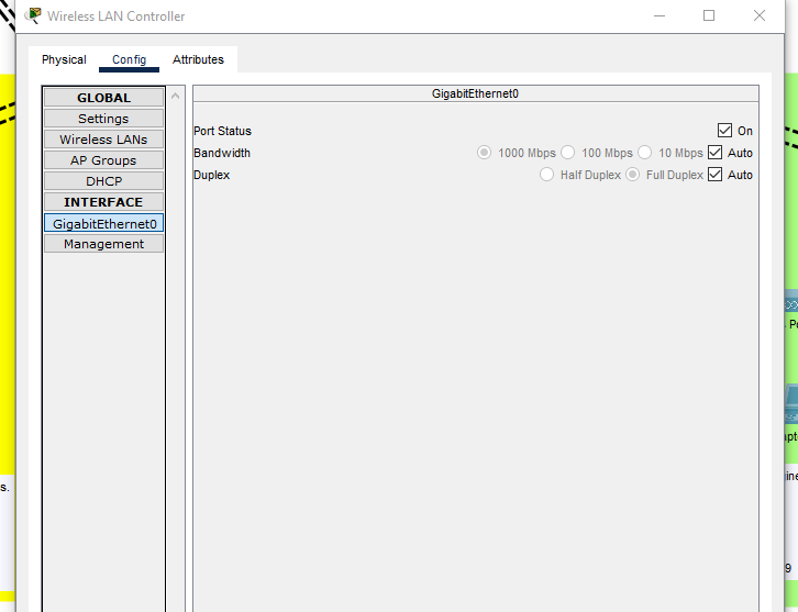
Configuring the Management interface on the WLC:

- In a real environment, the VLAN identifier for the management interface on the WLC would be the VLAN it is located in, which is VLAN150 in our network.
- After repeated experiments, this is not feasible in Packet Tracer as there’s a well known PT software bug that breaks the WLC connectivity once you change its Management VLAN. Therefore, we’re leaving the WLC Management as 0 (untagged). We’re setting native VLAN 150 on trunk ports connecting to the WLC and APs so management traffic stays untagged as well.
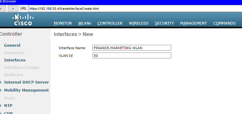
- Creating the dynamic interfaces that map the WLANs to their respective VLANs.
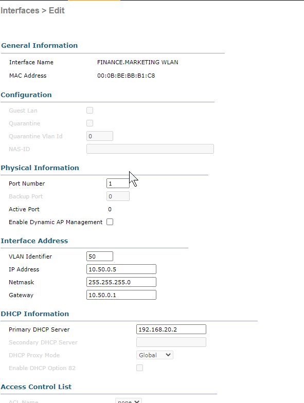
Configure the information necessary for the interface.
Don’t check “Enable Dynamic AP Management” as our Management Interface is providing that service already.
- In a production network with many APs, these roles would be separated across different interfaces for better scalability and performance.
- Management Interface: Initial AP discovery, CAPWAP tunnel formation, and provides administrative access to the WLC via SSH or HTTPs as the primary management IP address of the WLC.
- AP Manager Interface = AP management traffic after the APs joined already, ongoing communication. Handles continuous CAPWAP communication.
- Can have multiple AP-Manager interfaces to load balance if there is a large deployment of APs.
- Better scaling for environments with hundreds of APs.
- Better scaling for environments with hundreds of APs.
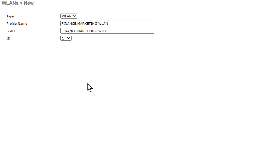
- Now we’re creating the actual WLAN (wireless network) that clients will see and connect to. This is where we configure the SSID (the network name users see when they search for Wi-Fi), along with security settings and VLAN mapping.

- Enabled. Ensure it’s mapped to the dynamic interface just created.

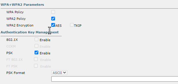
- Using WPA2-PSK although this is only the third best option here for security.
- Cannot use either of the 802.1X security options (which are superior) because we did not configure a RADIUS server.
- Static WEP should never be used as it is easily cracked and CKIP is deprecated.
- Ideally would use WPA3 as it offers superior security with Simultaneous Authentication of Equals and Protected Management Frames compared to WPA2 since we have no RADIUS server.
- AES is vastly superior to TKIP.
- WPA2 allowed use of TKIP for backwards compatibility but should never be used due to known vulnerabilities.
The next thing to configure are AP Groups. Here, we dictate which specific SSIDs each AP will broadcast. We do not want the AP for the HR and IT departments to broadcast the WiFi for the Finance department!
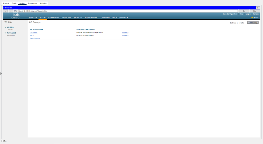
- Created AP Groups to organize access points and control which SSIDs they broadcast.
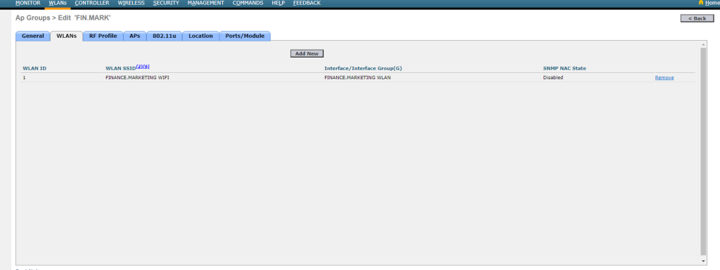
- Configuring the ‘FIN.MARK’ AP group with the ‘Finance.Marketing‘ SSID enabled, restricting member APs to broadcast only this SSID.
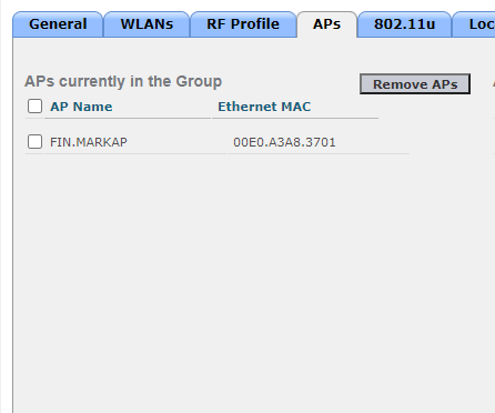
- Ensuring that the AP located in the Finance and Marketing Department is joined into the FIN.MARK AP Group.
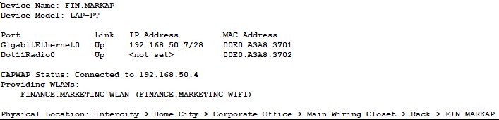
- Our AP in the Finance/Marketing Department established the CAPWAP tunnel to our WLC!
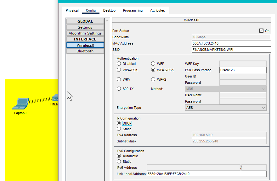
- A user’s laptop is able to connect to the WiFi and obtain an IP address from the DHCP server demonstrating seamless integration between the wireless and wired networks.
PAT Configuration
PAT will be implemented at our Edge Routers (non-DMZ traffic) for the following reasons:
- We want the firewall to focus solely on security filtering and policy enforcement, while the Edge Routers handle address translation and ISP connectivity, segmenting their duties optimizes each device for their primary role.
- Firewall-1 will still perform NAT for all DMZ-traffic but offloading internal user PAT to the edge routers significantly reduces the firewall’s processing burden. This preserves firewall resources for intensive security features such as deep packet inspection, intrusion prevention system and other security implementations the firewall will conduct to keep our network safe.
- FW-1 performs static NAT for our DMZ servers because our servers utilize sockets to track each unique TCP connection. Each connection is identified by its unique source IP and port combination, allowing thousands of users to simultaneously connect to the same destination port making PAT unnecessary here.
- Consolidating routing and PAT together at the network perimeter simplifies configuration and provides a single point of management for Internet-facing connectivity.
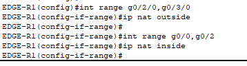
- Define what interfaces are facing inside (LANs) and outside (WANs) on our edge routers.

- Created an ACL that permits all of our LAN hosts.
- Note: – This is a NAT identification ACL, not a security ACL. It doesn’t block traffic – it simply tells the router which source IP addresses should be translated via PAT.
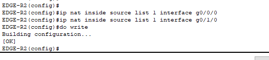
- Configured the router to reference “ACL1″ when performing PAT. When traffic from our internal LANs (that is ‘permitted’ by ACL 1) exits through the outgoing interfaces, the router will translate the source IP addresses to the public IP address configured on that outgoing interface.
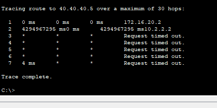
- Using “tracert” we see the ping from our host in VLAN20 is unable to reach an internet host. You can clearly see the ping dies at our firewall (10.2.2.2).
- Tracert only displays the last device that is able to respond, therefore we know the issue is with the firewall. The issue should lie within two possible causes:
- Either the firewall doesn’t know how to route out to the Internet (improbable because we know the firewall learned a default route through OSPF) or return traffic is being blocked by the firewall. Let’s troubleshoot the return traffic being blocked:
- In a production firewall, stateful inspection automatically allows return traffic for established connections. However, in Packet Tracer, either:
- Stateful inspection isn’t fully implemented or we need explicit ACLs to permit traffic from the Internet because stateful inspection isn’t working in Packet Tracer.
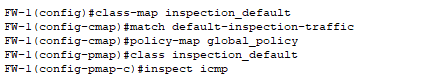
- Configured the commands necessary to ensure the firewall inspects all ICMP traffic globally, which should allow return ICMP echo replies due to these sessions being stateful.
- However, the pings still failed. I removed the “stateful inspection” commands from ICMP to now troubleshoot ACLs and isolate the issue.
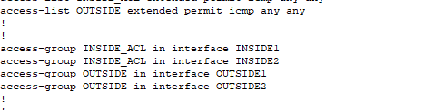
- Configured ACLs on my LAN-facing and WAN-facing interfaces:
- To improve redundancy and resiliency in our network, if the link between both Distribution Switches fails, traffic would have to flow from one DSW through a Firewall to reach the other side of the network. However:
- Cisco firewalls block traffic between interfaces with the same security level by default. The command to allow this (
same-security-traffic permit inter-interface) is not supported in Packet Tracer! - Which is the reason why we are also configuring explicit ACLs on inside interfaces.
- ACLs on the outside interfaces to explicitly allow return traffic (ICMP in this case). Stateful inspection should automatically permit return traffic when an internal host initiates the session but it appears that this doesn’t function properly in Packet Tracer, requiring explicit ACLs to manually permit return traffic.
- Cisco firewalls block traffic between interfaces with the same security level by default. The command to allow this (
- NOTE: Remember ACLs have an implicit deny any any at the end. In this scenario, all other traffic (HTTPs, SMTP) will be denied. This is a controlled, isolated project where we are simply testing basic connectivity between remote hosts using ping. In a production environment, you would need to add permit statements for all required protocols. Additionally, to reiterate, stateful inspection would normally have handled this automatically.
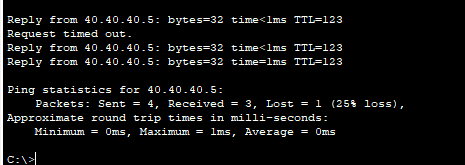
- And the pings worked! After configuring the explicit ACLs, pings from our LAN hosts to Internet destinations are now successful.
- After researching this issue, I discovered that firewalls within Packet Tracer do not properly implement stateful inspection. Therefore, in a real Cisco firewall – the class and policy maps we configured would have been sufficient to allow return traffic for established sessions.
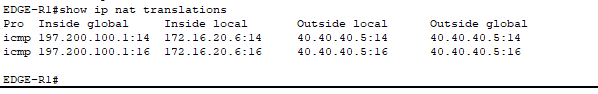
- We see PAT working on our Edge Router!
The final thing we need to configure for PAT is to ensure that Firewall-1 performs static-NAT for our public-facing servers located in the DMZ. The reason we want the firewall to perform this function instead of the edge router is because:
- This configuration provides tighter control over the DMZ and enables specialized NAT policies like static NAT for our public-facing servers.
- We want to centralize all of our DMZ security into the firewall.
- We want complete session visibility where the firewall tracks the full NAT session which will provide more insight regarding any security event correlation for DMZ traffic.
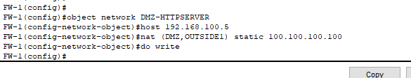
- This is how you configure static NAT on a firewall.

- Remember our prior issues where we needed to explicitly allow return ICMP replies with an ACL even though stateful inspections should be sufficient due to security-levels.
- Recall we already configured ACLs permitting ICMP traffic on the interfaces facing the Internet and LAN hosts.
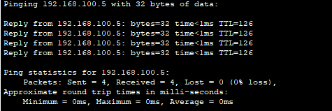
- A host in our private LAN can ping the DMZ server!
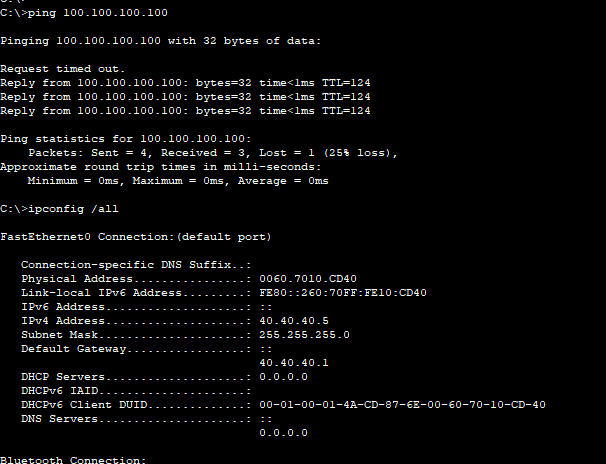
- Our Internet host beyond our ISP routers is able to ping our web server within our DMZ!
VoIP Configuration
- What we’re going to configure on our Voice Gateway is the Call Manager functionality. In a typical enterprise deployment, the Voice Gateway would route external traffic to/from the PSTN network (allowing external calling), while a separate Call Manager server would handle internal phone services. However, Packet Tracer does not simulate PSTN connectivity, so in this topology, we’re configuring the Voice Gateway to act solely as the Call Manager server.
- The Call Manager’s function is to assign extension numbers to internal phones as well as handle internal call routing.
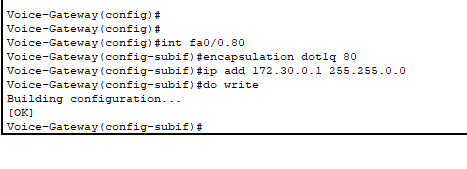
- Begin by configuring the subinterface on the Voice Gateway connected to ASW4.
- Remember: all of our VoIP is in one VLAN: 80.
- Same commands as “router-on-a-stick”.
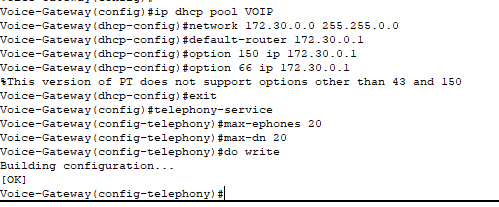
- Creating the DHCP pool for our IP phones to obtain the necessary configurations for connectivity.
- Included Options 66 and 150 that tells the IP phones the location of the TFTP server where they can download their configuration files from.
- Option 66 if you’re environment is multi-vendor and you can also utilize hostnames instead of just IP addresses (however Packet Tracer does not support this as evident above).
- Option 150 is for Cisco IP phones only, no hostnames.
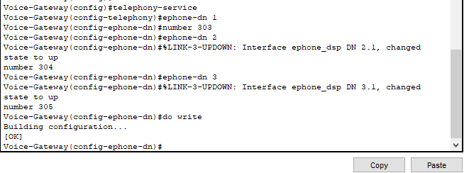
- Mapping phone extensions to directories.
- For example: whichever IP phone gets assigned ephone-dn 1 will have its primary extension to reach it as 303.
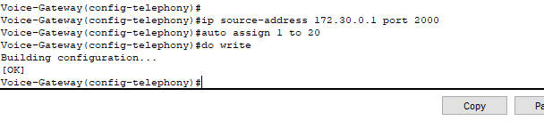
- IP Phones need to get on the network through a DHCP service to be able to even communicate and be configured with the correct configuration files (downloaded from TFTP server as instructed by DHCP). Then, they need to register with a Call Manager to get an actual phone identity (or extension number).
- Therefore instructing our IP phones to communicate with our Voice Gateway router using port 2000 to register with SCCP/SIP.
- Configured auto assign so whenever the IP phone communicates with our CME for SCCP/SIP registration, it automatically assigns it the next available extension number.
- The CME handing out extensions is on a first come, first serve basis – there is no way of guaranteeing a specific phone to obtain a specific extension number utilizing this command.
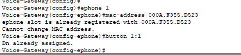
- However, you can bind the MAC address of the phone to a specific ephone-dn (directory) to guarantee that phone receives that specific extension number. This is the method we’d typically use so we can group extensions numbers to departments and provide structure.
- The above commands display how you would configure this scenario.
- Here, ephone-1 (that has the MAC address configured above) will be guaranteed to receive whatever extension is mapped to the directory of ephone-1. Additionally, the first button on the physical phone is mapped to the extension 303 (the number mapped to ephone-dn 1).
- You must configure each e-phone with the corresponding MAC address and button prior to powering on the phones before the DHCP server gives them the necessary information.
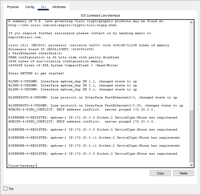
- As you can see our IP phones have registered with the Call Manager and have obtained their extensions.
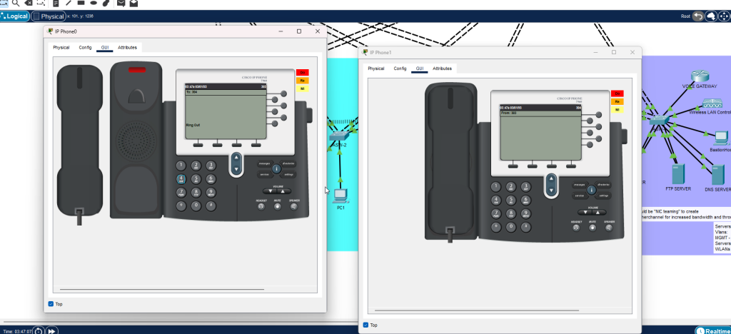
- Our first IP phone with the extension 303 is calling our second IP phone with the extension 304.
- Our VoIP configuration is complete!
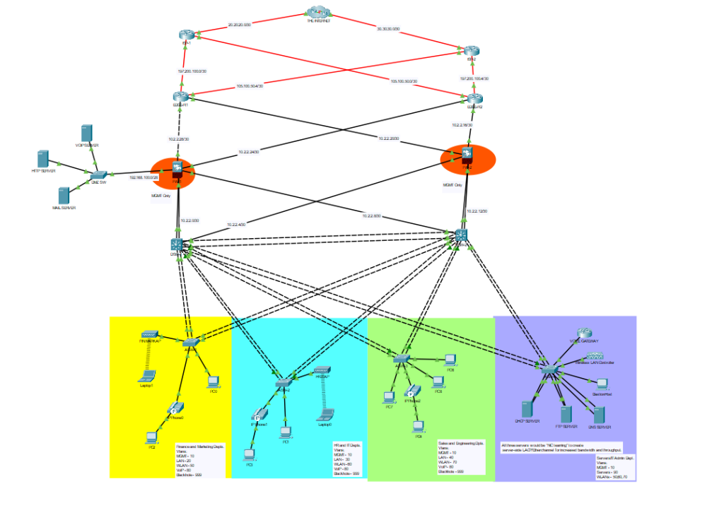
- And this is our final network topology!