Network Lab 2 – VLANs, Subnetting, Advanced Configuration
Project Overview
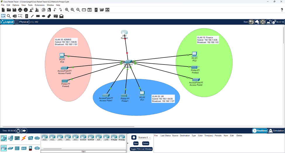
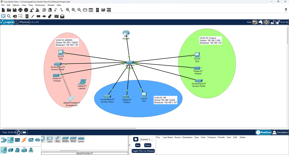
Building on the fundamentals from Project #1, this project expands into enterprise-level network segmentation. The goal is to create a network divided into three separate departments, each with their own VLANs. We will configure management IP addresses on the Layer 2 switch to allow for remote administration. Each department will connect through a central switch that links to a router using the router-on-a-stick method. The router serves as the DHCP server for all hosts, and we’re implementing Port Address Translation (PAT) to conserve the limited public IP addresses provided by our ISP.
For this project, we’re working within the constraints of the 192.168.1.0/24 network to dive deeper into subnetting concepts.
Note: In real-world environments, you’d typically segment LANs using the entire 192.168.x.x range for simplicity since it’s all private and not routable to the Internet. For example, VLAN 10 might use 192.168.10.0/24, VLAN 20 would use 192.168.20.0/24, and so on.
- If your LANs need more than 254 hosts per VLAN, you have a couple of options:
- Use the other private IP ranges: 10.x.x.x or 172.16-31.x.x, which give you significantly more addresses to work with.
- Stick with the 192.168 range but use a large subnet mask such as /20 instead of /24.
- Example with using /20 subnets: If we carved up the 192.168.0.0/16 range into /20 subnets, we’d get 16 different subnets, each supporting up to 4,094 usable hosts.
Subnetting the 192.168.1.0/24 Network
Since we need to divide this network into 3 departments, we need at least 3 different subnets. Using the formula 2^n (where n = borrowed host bits), we can see that:
- Borrowing 1 bit gives us 2 subnets which is not enough.
- Borrowing 2 bits gives us 4 subnets which does work.
- For the fourth subnet, we’ll use it as the Management VLAN to separate management traffic from regular data traffic, increasing segmentation and improving our security posture.
- In a real environment, you’d typically segment this management VLAN even further to reduce its attack surface.
- For the fourth subnet, we’ll use it as the Management VLAN to separate management traffic from regular data traffic, increasing segmentation and improving our security posture.
Subnet Breakdown:
- Original network: 192.168.1.0/24 (24 network bits).
- After borrowing 2 host bits: /26 network (26 network bits).
- Remaining host bits: 6 bits.
- Usable hosts per subnet: 2^6 – 2 = 62 usable hosts (we always subtract two hosts for each subnet due to the network ID and broadcast address which are always the very first and last addresses in each space).
- IPv6 does not have this limitation.
Binary Representation:
- Original /24: 11111111.11111111.11111111.00000000 (255.255.255.0)
- New /26: 11111111.11111111.11111111.11000000 (255.255.255.192)
- The subnet mask (255.255.255.192) is extremely important later on.
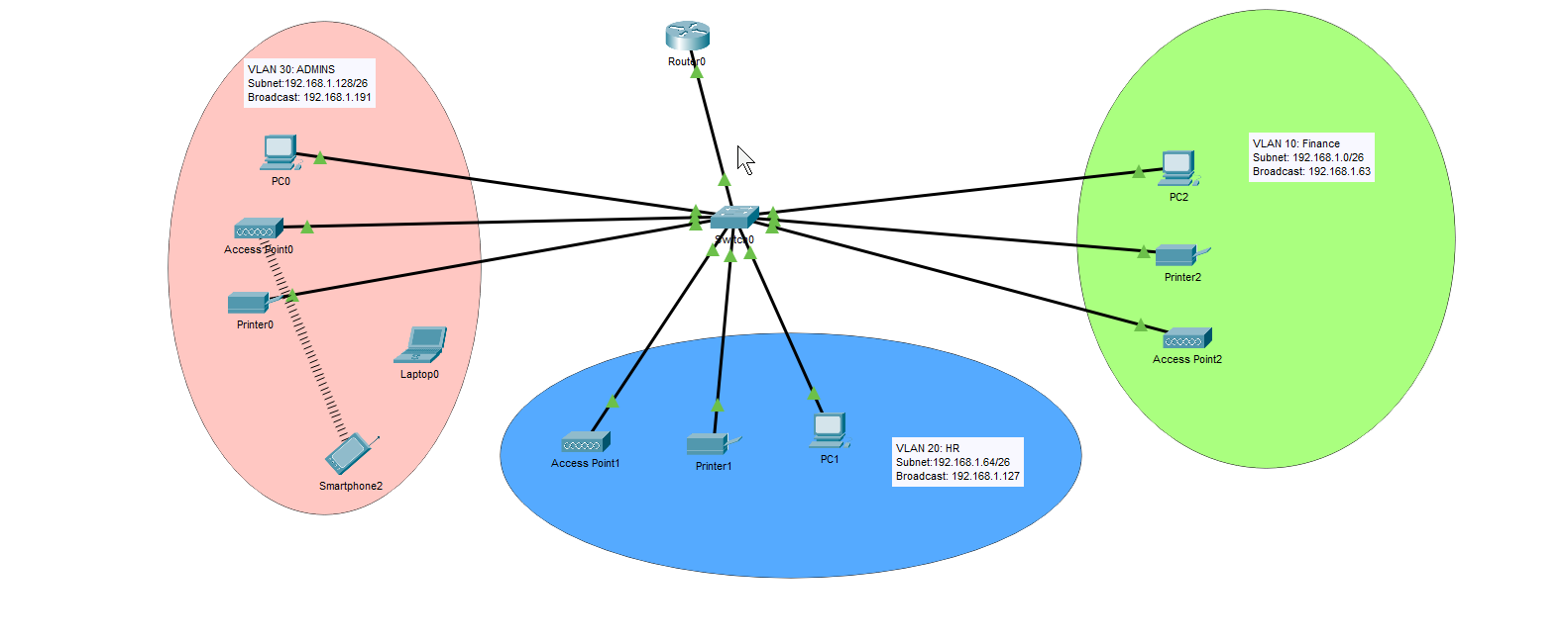
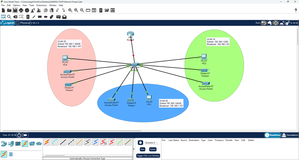
Subnet Allocation:
- Department A: Using VLAN 10, 192.168.1.0/26 (192.168.1.0 – 192.168.1.63).
- Department B: Using VLAN 20, 192.168.1.64/26 (192.168.1.64 – 192.168.1.127).
- Department C: Using VLAN 30, 192.168.1.128/26 (192.168.1.128 – 192.168.1.191).
- Management Subnet: Using VLAN 101, 192.168.1.192/26 (192.168.1.192-192.168.1.255) – remember this would actually be segmented further.
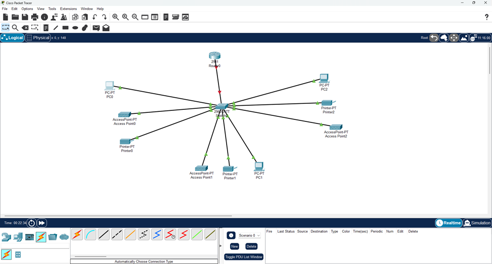
Identifying Connected Devices
Now we face a common challenge: all hosts are connected to the switch, but we need to figure out which device is plugged into which port. There are several approaches to handle this:
Real-World Methods:
- Documentation: In enterprise environments, there should be existing documentation showing which devices connect to which ports. Ideally, someone documented this in real-time during the initial cable installation.
- Naming Standards: Companies may follow specific connection schemas (like PC1 to Port Fa0/1, etc.) to keep things organized.
- MAC Address Analysis: If you are new to an already established network, the end hosts should have already obtained IP addresses (either statically or through DHCP). Using the command “show mac address-table” on the switch, you can identify which MAC addresses are associated with each port.
- This works because switches store the source MAC address of frames they receive.
- We are assuming each device has already sent at least one frame so the switch has populated its MAC table.
- This works because switches store the source MAC address of frames they receive.
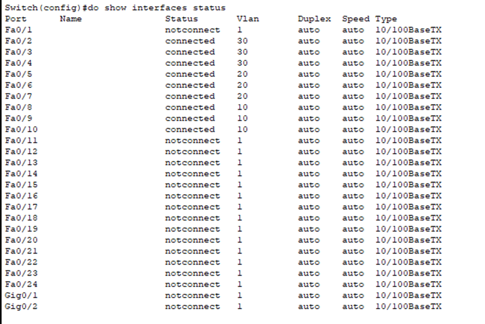
- Physical Testing: During maintenance windows, you can systematically unplug cables and check which devices lose connectivity. You also can see which switch ports go down using the “show interfaces status” command or by looking at the link lights.
Project Method Used: I generated DHCP Discover messages using ipconfig /renew because:
- It’s a broadcast frame (so the switch will flood it out) that doesn’t require an existing IP address.
- The switch can populate its MAC address table from this traffic.

- If I tried using “ipconfig /release” instead, I would get this error and no DHCP traffic would be generated because there was no IP address to release.
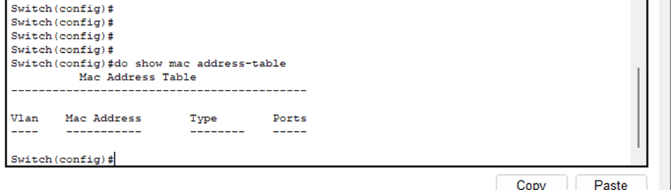
- You can clearly see that no traffic was generated.
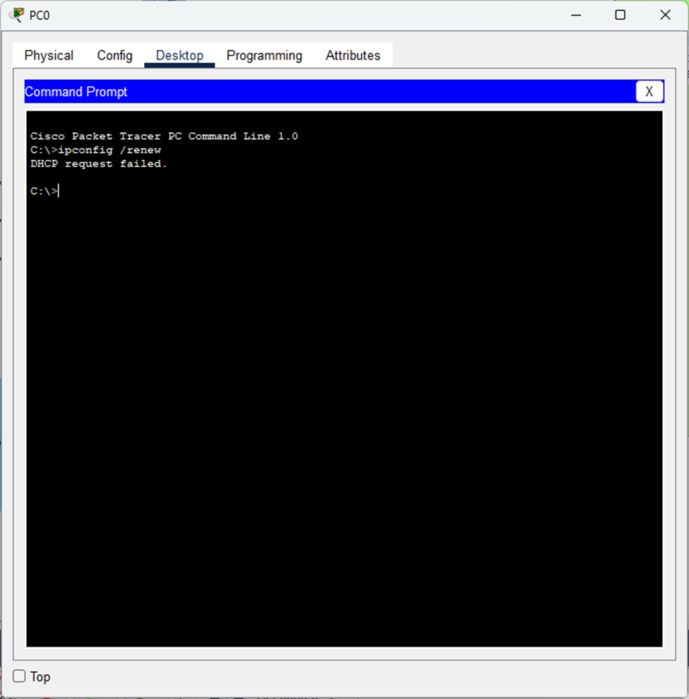
- But when I use “ipconfig /renew”..
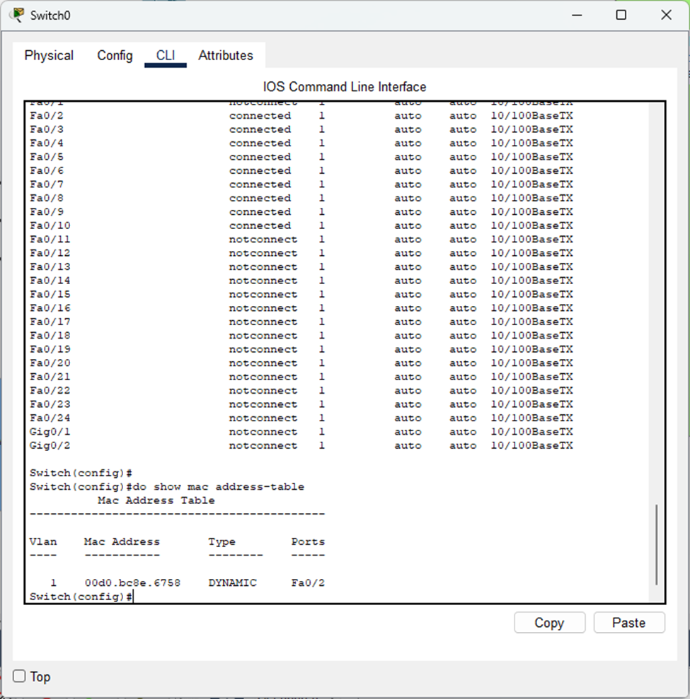
- The command worked perfectly – you can see the PC’s MAC address now appears in the switch’s MAC table, identifying which port it’s connected to.
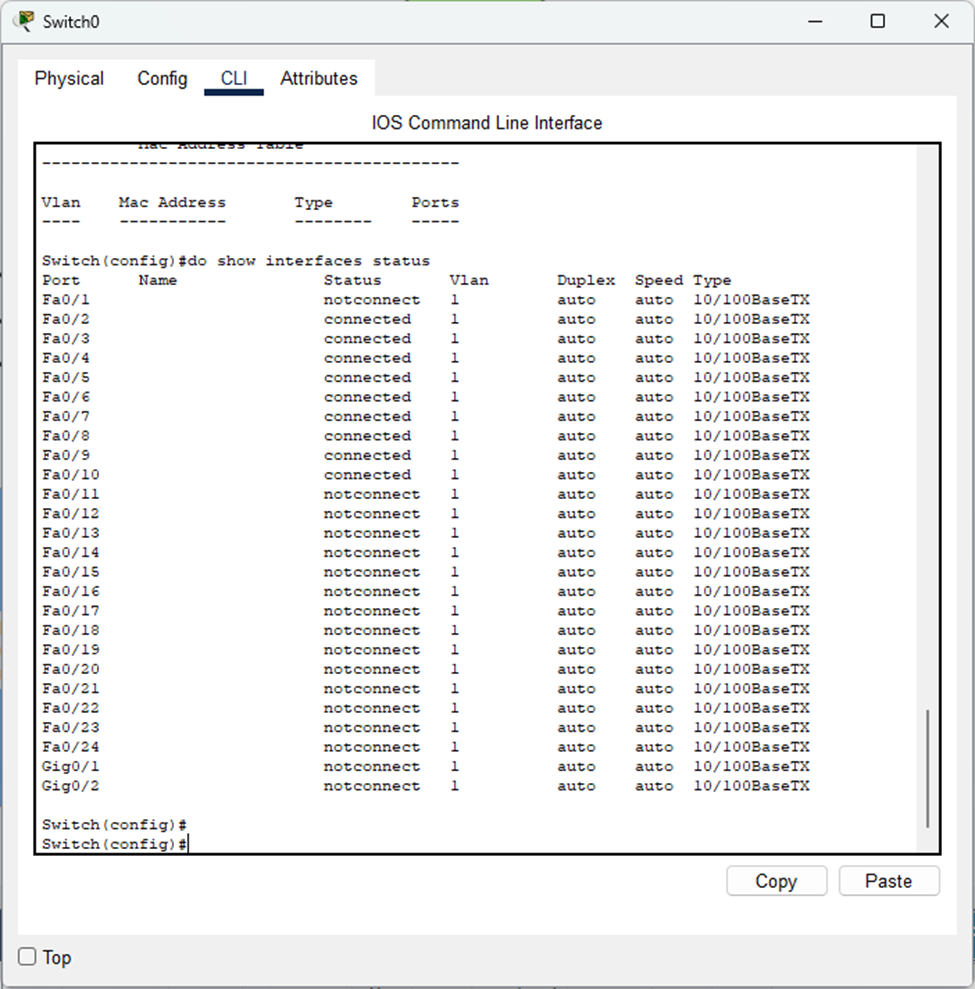
- The port connected to the router is “not connected” (even though they are physically connected) because the router port is still shutdown- we’ll fix that in a bit.
VLAN Configuration and Access Ports
Time to configure our ports connected to the end hosts as access ports. This ensures each port only carries traffic for its assigned VLAN, providing network segmentation and security.
- Devices in VLAN 10 can only communicate within VLAN10 (without the use of a router).
- This keeps broadcast domains separate and prevents unauthorized access between departments.
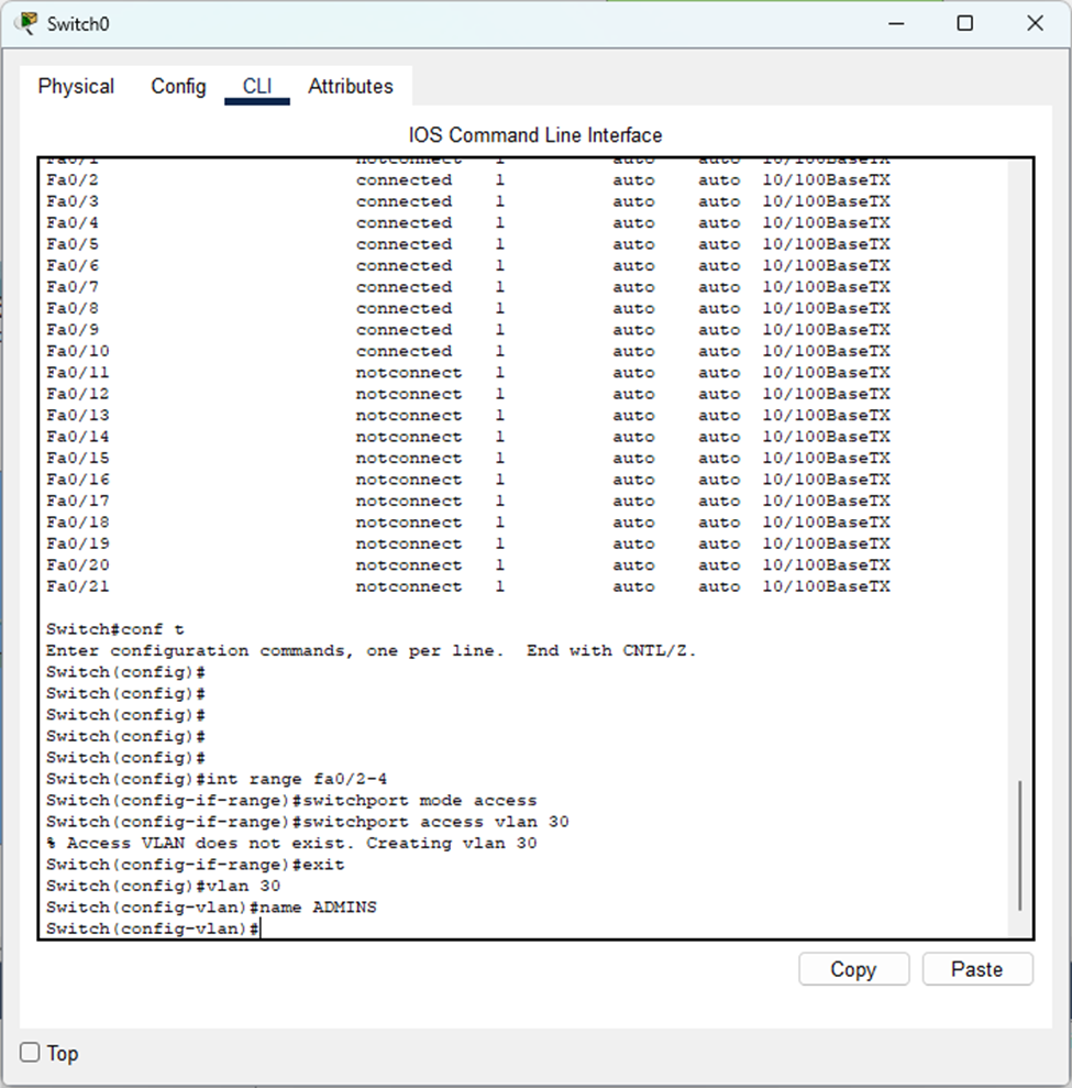
- Each department gets its own VLAN with a descriptive name. Remember to save your configurations using the “
write", “write memory", or “copy running-config startup-config“ commands.
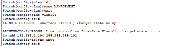
With our VLANs configured, it’s time to give the switch itself an IP address for management and enable SSH. This will let us manage the switch remotely instead of always needing console access. Remember those SSH configuration steps from Project #1?
Router-on-a-Stick Implementation
Since we’re using a Layer 2 switch, it can’t route traffic between VLANs – that’s just not what it’s designed to do. Each VLAN exists as its own isolated network and needs a router to communicate with the others.
Note: Layer 3 switches can route between VLANs, but that’s for another project.
Trunk Link Configuration: The connection between the switch and router needs to be configured as a trunk because trunk links can carry traffic for multiple VLANs over a single cable.
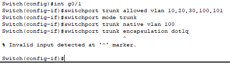
- I tried to specify
"switchport trunk encapsulation dot1q“ but received an error. This is actually a good thing because it means that the switch only supports 802.1Q for VLAN tagging (the industry standard). Older Cisco switches support ISL ( a deprecated Cisco proprietary protocol) in addition to 802.1Q, but modern equipment has moved away from it thus we did not have to configure this.
Security Implementation:
- Limited allowed VLANs to only those we configured, plus VLAN 100 as our native VLAN.
- Changed native VLAN from default (VLAN 1) to VLAN 100 to prevent VLAN hopping attacks.
- The native VLAN handles all untagged frames that come through the trunk link. When a frame arrives without the 802.1Q tag in its header, the switch automatically assigns it to the native VLAN.
- As VLAN 100 has no hosts in it, it is an isolated network. Only management and control traffic such as CDP/LLDP, STP/RSTP, LACP, etc. would traverse through this VLAN.
Don’t forget to create VLANs 100 and 101!
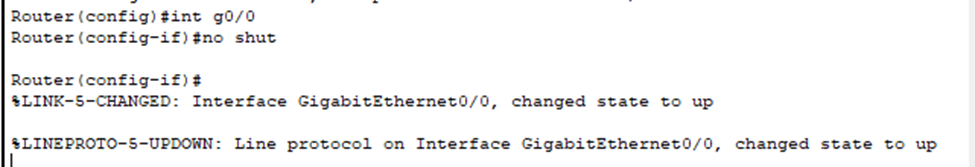
- On routers, all interfaces are administratively down by default therefore you must use the “no shutdown” command on whichever interface(s) you want to bring online. This is not necessary for switches unless it is a routed port (Layer 3) or SVI (which we just configured for our management IP address).

Subinterface Configuration: Now we create subinterfaces on the router’s physical interface connected to the switch.
- Each subinterface corresponds to a specified VLAN and receives their own IP address that serves as that VLAN’s default gateway.
- Hosts in each VLAN are configured to use their respective subinterface as their default gateway.
- When a host in VLAN10 needs to send traffic to VLAN20, it sends its frame to the router’s subinterface for VLAN10, router receives it and conducts its routing process and recognizes it must be sent to a different VLAN. It forwards it out the VLAN20 subinterface and the frame is tagged with VLAN20 down the trunk link so the switch can appropriately send it to the correct destination host.
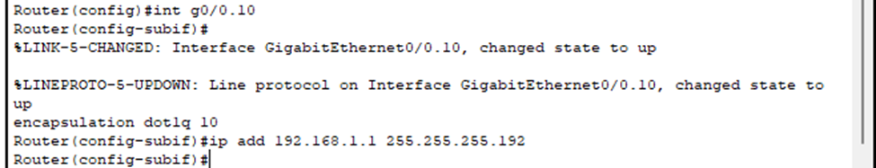
- To create a subinterface, you specify the physical interface followed by .x (where x is typically the VLAN number). Example: interface Fa0/0.10
- You’ll notice the the command line switching to “config-subif”.
- Must use “encapsulation dot1q [vlan#]” to indicate to the router to use 802.1Q tagging and for which VLAN this subinterface is for.
- Then, you configure the actual IP address and subnet mask which will be the default gateway.
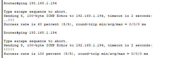
- Using the router, we pinged the switch’s management IP address we configured and noticed we can reach it.
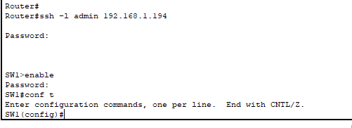
- I am now able to SSH into the switch from the router meaning I can fully manage the switch remotely without needing console access.
- You wouldn’t SSH from one network device into another like this. Instead, you’d use a dedicated management workstation or bastion host that’s either located in the same management VLAN or in a different VLAN with proper ACL configuration to allow it to access the management VLAN.
DHCP Server Configuration
Time to configure the router as a DHCP server so our hosts can automatically obtain IP addresses:
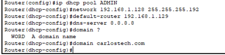
For each VLAN, we configure a separate DHCP pool. Each DHCP pool needs these key settings:
- Domain name: Provides a local domain for the hosts.
- Network range: The subnet the DHCP server can assign addresses from (192.168.1.0/26 for VLAN10).
- Default gateway: Points to the router subinterface for that VLAN.
- DNS servers: Using Google’s public DNS (8.8.8.8) since we’re not running a DNS server on our router.
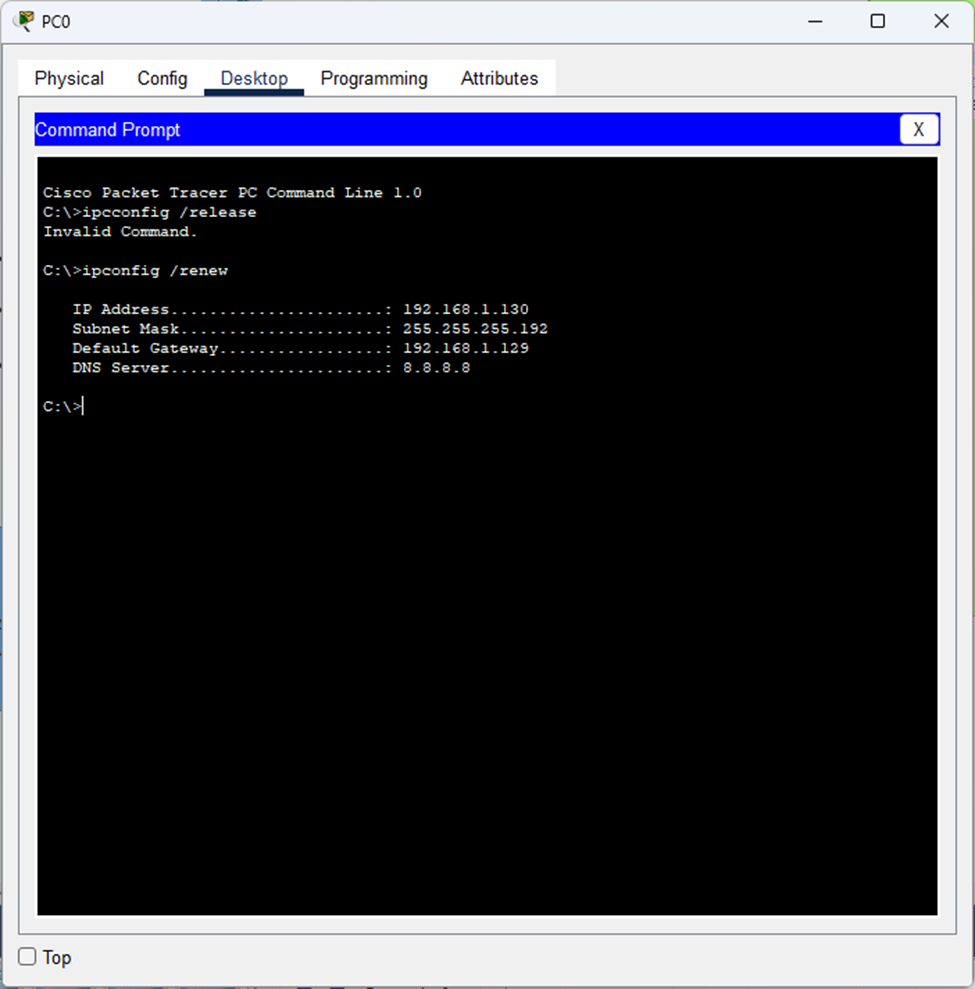
- Remember how this command didn’t work before? Now our PC has successfully received an IP address from DHCP and is able to communicate with other devices on the network.
- Typically, we also configure lease duration in which you indicate how long you want devices to keep whatever IP address the DHCP server reserved to them. You do not want one device keeping an IP address from the pool you configured infinitely which could quickly exhaust your IP pool.
- If the device disconnects, they can still keep that IP address!
Let’s check if the PC in VLAN 30 can communicate with the PC in VLAN 10:
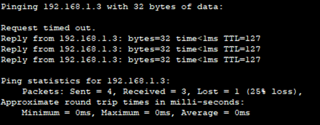
And it worked! Inter-VLAN communication is working.
The PC from VLAN30 sent the frame that is encapsulating the ping packet, to its default gateway. The switch received this frame and forwarded it through the trunk link with an 802.1Q tag for VLAN30. The router then receives it on the subinterface for VLAN 30 where it strips the frame header and trailer to read the destination IP address. The router makes its routing decision, adds an 802.1Q tag for VLAN10 and sends it back through the trunk. The switch receives this tagged frame, and forwards it out to the correct VLAN10 access port.
Wireless Network Integration
Now let’s add wireless capability to each department so users can connect via Wi-Fi in addition to the wired connections.
Note: This will be a basic wireless setup to get things working. We’ll dive into advanced wireless topics in the next project.
Configuring the access point in the Admins department:
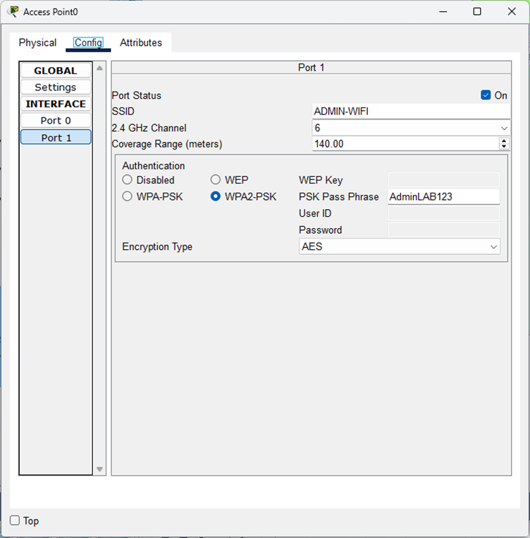
Configuration:
- SSID: Department-specific network name for easy identification (this is what you see when you search for Wi-Fi networks).
- Authentication: WPA2-PSK is the most secure option available on this AP.
- WPA3 would be better if the AP supported it and is the standard.
- Encryption: AES is significantly more secure than the older TKIP standard.
- Always use Advanced Encryption Standard when possible.
- Channel Planning: Since this AP operates on 2.4GHz, if deploying multiple APs in proximity, you must only use channels 1, 6, and 11 to minimize interference and provide seamless wireless connectivity. These are the only non-overlapping channels for 2.4GHz.
- Example: AP1 on channel 1, AP2 on channel 6 and AP3 on channel 11.
- If this was a 5 GHz AP, you’d have significantly more non-overlapping channels and therefore would be able to have looser channel planning.
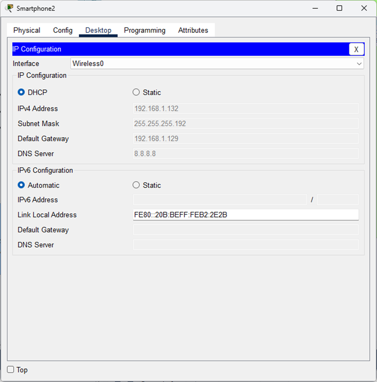
You can see that the smartphone successfully connected to the wireless network and obtained an IP address from our DHCP server, demonstrating full integration between wired and wireless infrastructure.
Port Address Translation (PAT) Setup
All our hosts have private IP addresses that aren’t routable on the Internet. They’re using Google’s DNS servers to resolve domain names, so how does a user reach youtube.com?
Due to IPv4 address exhaustion, our ISP has allocated us only two public IP addresses: 204.113.5.6 and 204.113.5.7. These two public IP addresses are what we use to communicate beyond our router – to the actual Internet. Hosts on the Internet identify us with these two public IPs.
The Challenge: How do hundreds or even thousands of internal devices access the Internet using just two public addresses?
The Solution: Port Address Translation (PAT), an extension of Network Address Translation (NAT). PAT maps multiple private IPv4 addresses to a single public IP address by using different port numbers to track individual sessions and connections. This technology has been crucial in managing IPv4 address exhaustion.
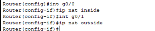
- The first thing we must do is configure which interface is the inside interface (pointing to your internal networks using private IPs) and which one is the outside (pointing to the internet where public IPs are utilized). This tells the router which direction needs translation (private -> public when going out, public -> private when coming back in).
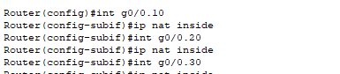
- Note: You must configure “ip nat inside” on each subinterface individually since they are all logical interfaces in our router on a stick setup.
- If you only mark the physical interface, the subinterfaces will not inherit the NAT setting.
- Next, we need to configure an Access Control List (ACL) that will define which IP addresses should be translated. In our case, it would be all hosts in our three departments.
- The management VLAN devices will not be translated because they typically do not need direct Internet access.

I created a standard ACL that permits the entire 192.168.1.0/24 network (this covers all 3 department VLANs).
- ACLs use wildcard masks in which the masks are inverted. 0.0.0.255 is the same as 255.255.255.0.
- ACLs have an invisible “implicit deny” at the end. Any traffic not explicitly permitted will be automatically denied
Note: ACLs only take effect when applied to an interface or referenced in a configuration (like NAT). Creating an ACL without applying it has zero impact on traffic flow.
Instead of using a single interface IP, we’ll create a pool utilizing both public addresses, which provides better load distribution and utilizes both public IP addresses more efficiently.

- Here I created a NAT pool – similar to how we configured DHCP pools earlier, but instead of defining private IP addresses to assign to hosts, we’re defining the public IP addresses that NAT can translate to.

- PAT has been configured. We are telling the router to look at ACL 1 to check which internal IPs need translation. If they are eligible, use the pool “PUBLIC_IPs” to determine which IP address are available to translate to. Finally, telling the router to use PAT (overload) to allow hundreds or thousands of hosts to share the same public IP by using different port numbers.
- There are 65,535 ports available. Depending on router implementation, performance limitations, and other variables – PAT can potentially have 60,000-65,000 concurrent connections PER public IP.
Note: If there was another network here that would be “implicitly denied” such as 10.0.0.0/8, its traffic wouldn’t be dropped because of the ACL – it would be dropped because the router didn’t translate its private IP to a public one and private IPs are not routable on the public Internet.
To see which internal host(s) are using which public IP and the port number for the session, you’d use “show ip nat translations”.
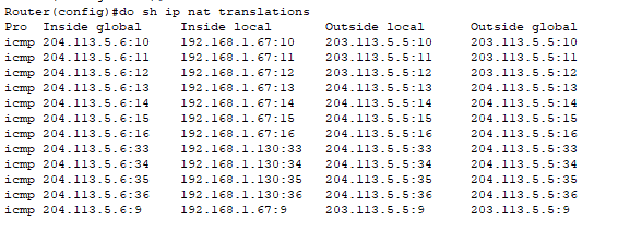
PAT is working!
What you can see in the translation table:
- Two different hosts (192.168.1.67 and 192.168.1.130) as shown by their inside local addresses.
- Both sharing the same public IP address (204.113.5.6) shown as the inside global address.
- Each connection is being tracked with different numbers appended (:10, :11, :12, etc.).
- Note: Since we’re sending pings (ICMP), those numbers aren’t actually ports as ICMP doesn’t use port numbers. Instead, NAT is using the “ICMP Query ID field” and displaying it as if it was a port number for tracking purposes. Each ping packet can have a different Query ID, which is why we see those different numbers (:10, :11, etc.).
- For TCP/UDP traffic (basically when you connect to any application), you’d see actual port numbers being used. But the concept is the same: PAT is successfully allowing multiple internal hosts to share one public IP by using different identifiers to keep track of each session.