Network Lab 1- Device Hardening and Initial Configurations
Summary
This is the first project in the Network Project series. Each project introduces progressively complex network scenarios and builds upon previous concepts. This initial project focuses on device hardening and fundamental subnetting. Future projects will incorporate these concepts but shift focus toward more advanced topics.
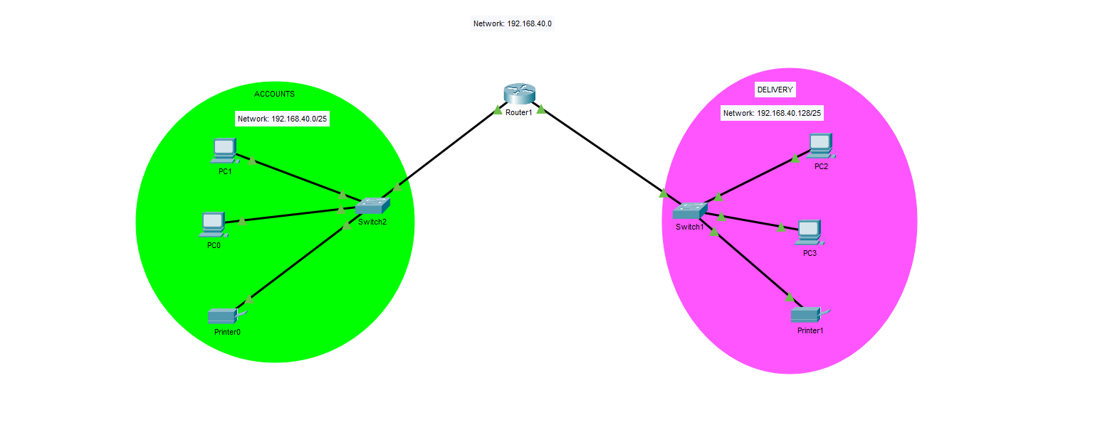
Scenario: We have a company that wants to divide the 192.168.40.0/24 network between two internal departments, Accounts and Delivery. Each department must have at least 2 PCs and the appropriate amount of switches and routers.
- This is the initial diagram we are utilizing for this project. Only one router is needed between both LANs, and one switch per LAN. It is great practice to segment each department into their own LAN for security purposes, which will also improve network performance (less broadcast frames).
- VLANs are not necessary here because each LAN is connected to a separate switch. If there were multiple LANs or departments connected to a single switch, Virtual Local Area Networks are absolutely necessary to segment traffic. Switches reduce each link to a single collision domain – but if all are in the same subnet, it is still one broadcast domain.
- In a real environment, these two departments would absolutely be connected to the same switch and would require VLANs in order to save costs. Switches can allow for up to 24+ hosts to connect to them.
Implementation Details
Securing the Devices
The first thing you typically do to a new machine is to connect to it with a console cable (initially the only way to enter the machine) and begin doing initial configurations on it. Some of these initial configurations would be:
- Changing the hostname to whatever operational standard your company uses.
- Downloading the current version IOS file from your TFTP or FTP server.
- Setting up the VTY, console and enable passwords to secure access to the console port, SSH lines and privileged EXEC mode.
- Setting up secure shell (SSH) – an extremely secure way of remoting into the CLI of a machine. The other method is using Telnet (port 23) but you should never use this protocol – as it is not secure! In fact, you should disable the ability to Telnet into your machines completely.
- Setting up management IP addresses on network devices so you can remotely manage them.
- In this step, you typically place these management IPs into a management subnet that is isolated from the actual network. Only admins should have access to this network.
- We will configure this step in our next project, which will contain VLANs, because to create management IP addresses on a Layer 2 switch, you must use the concept of VLANs – which we’re not discussing further in this project.
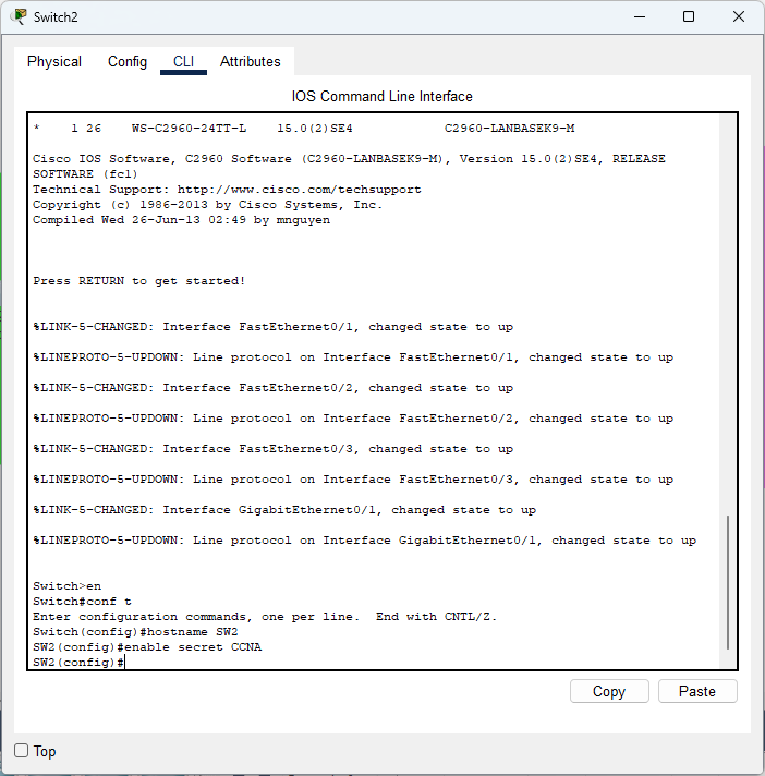
- Here we are changing the hostname of our machine and setting up a secure password to reach privileged EXEC mode. You should never use the ‘password’ command as it not secure – use secret!
- Due to Packet Tracer limitations the command I’d ideally use is “enable algorithm-type sha256 secret” instead which will not show the password your configuring in plaintext. It is not stored in the command history (enable secret does) and sha-256 is a stronger hash than MD5.
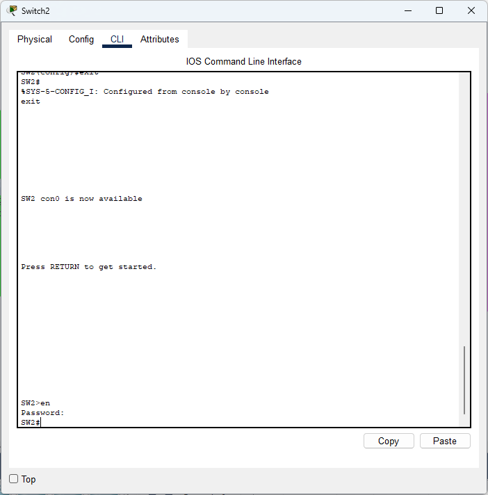
- Now the switch asks me for the password. Obviously, CCNA is not a good password whatsoever. You should have at a minimum, 12+ characters (more is better), with sporadic uppercase and lowercase letters, using numbers as well as symbols such as “!”. Now our privileged EXEC mode is protected.
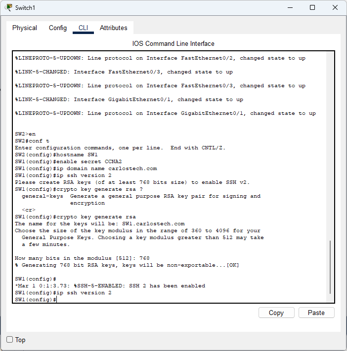
- We tried to enable SSH version 2 only (more secure) but we needed to create the RSA keys first because version 2 only allows a minimum of 768 bit size RSA keys. To do that, you need to change the hostname of your machine (done already) and configure a domain, which we did to “carlostech.com”. Now our SSH keys are generated and we can enable the use of SSH version 2 only.
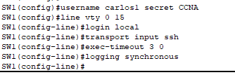
- For SSH to work, we need to create a local username and password. We configured the switch so whenever someone tried to SSH in any of the 16 lines available, they will be prompted for a local username and password. We also restricted all vty lines to SSH only because Telnet is insecure.
- Note: another secure method for authentication is by using a RADIUS server (provides AAA services) which would query your Active Directory server to confirm if said user should be authenticated.
- RADIUS servers are able to query AD while network devices are not which is why both devices work hand in hand. RADIUS is the middleman while AD actually stores the username/password database.
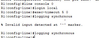
- The above image shows how to properly secure the console port. Since there’s only one console port, use “line console 0″ and we use the same login local command we used to secure the vty lines. Two commands that weren’t explained earlier: “exec-timeout 5 0″ and “logging synchronous”, the former command automatically logs you out after five minutes of inactivity and the latter command does not allow log messages to interrupt your commands.
Downloading the IOS Image File
We want to download the current IOS version so our network devices reach the operational standard of the organization. TFTP (Trivial File Transfer Protocol, port 69) is less secure than FTP (ports 20 and 21), but provides quick file transfers. You usually use this because you should be downloading files within a trusted, secured and isolated network. Your security policies regarding network segmentation, ACLs, firewalls and more are what provides the security. However FTP is not as secure as you may think – it requires authentication, but there’s no encryption and everything is sent in plaintext. You use FTP for larger file transfers and when authentication is required.
For FTP, you must configure the router with the username and password that is already configured on the FTP server. They must match so the router can present these credentials to the FTP server when prompted. TFTP does not prompt for a username or password.
- Additionally, FTP has a bottleneck where the networking device can only store one set of FTP usernames and passwords. What if there are several different FTP servers in a highly secure environment? These are the workarounds:
- Configure the FTP username and password one a time before you have to access each FTP server. When you add a new set of username and password, it overwrites the old one. This is a massive security risk and not ideal whatsoever.
- If you do not want to configure a new set of username and password for each FTP server, you can embed the credentials into your command such as “copy ftp://username:password@192.168.40.5/filepath flash:” – this is an even bigger vulnerability because the username and password will show in plaintext in the machine’s history.
- Upgrading to using SFTP (Secure Shell FTP) completely alleviates this issue. SFTP has the full file functionality of FTP but runs over SSH.
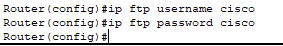
- Configured the username and password the router would give the FTP server when prompted.
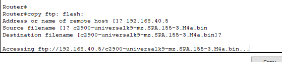
- The command structure used to copy a file from the FTP server into the flash memory of the network device.
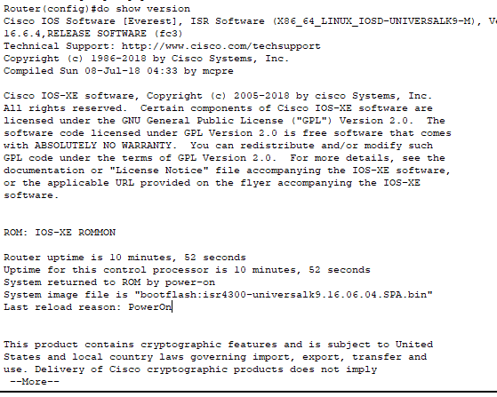
- Using “show version” command to see which IOS file is currently the boot file for the router.
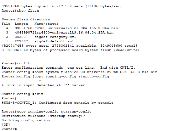
- In the above image you can see that the FTP file was copied into the flash memory of our router and we configured the router so it boots with the IOS file we copied.
- Remember to save to your start-up configuration using either “copy running-config startup-config” “write”, or “write memory” and then reloading the machine (obviously during planned maintenance windows).
For robust security and the standard in modern networks, we would use SFTP. It works on port 22 and provides the best security in encryption and authentication when transferring files. The FTP server has to have SSH enabled on it but the command syntax is similar: “copy sftp: flash:” which would then prompt for the same information as our FTP example.
- Due to Packet Tracer limitations, I am unable to show an example of SFTP.
Physical Infrastructure Setup
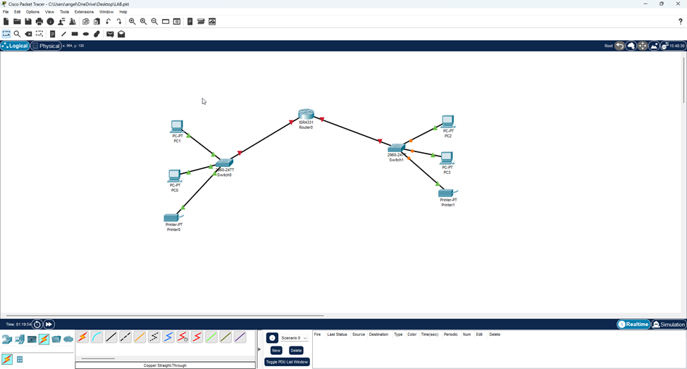
The second thing required is to connect each machine with the correct cables. Use crossover Ethernet cables if connecting two devices that are similar (they have their transmitter and receiver pins in the same places). Examples: router to router, pc to router and switch to switch. You use a straight-through (patch) Ethernet cable if the devices are different (different transmitter/receiver pin locations). Ex: PC to switch, switch to router. In this case, we used patch cables for all connections.
- Use proper cable labeling and cable management. We would want to use Cat 5e or Cat 6 cables for high speed.
- Note: With Auto-MDIX, which most modern devices have, you don’t have to worry about what kind of cable you’re using. The devices can detect the pins and dynamically reassign pins.
Subnetting
The company has the 192.168.40.0/24 network, but since only two departments are going to use it, we need to know which sub mask to use to appropriately divide the number of subnets as well.
- Note: The 192.168.x.x is considered a PRIVATE IP network. This range of IP addresses (192.168.0.0 – 192.168.255.255) was set aside so organizations can use this range internally, without ever having to worry about duplicate addresses on the Internet. Every organization in the world can have these same IP addresses and no issue would arise; these addresses are not globally-routable. The other ranges of IP addresses set aside that are non-routable and private are: 10.0.0.0-10.255.255.255 and 172.16.0.00-172.31.255.255. To communicate with the Internet, a router performs NAT (or more realistically, PAT) but this is for a future project.
Since the company asked us to divide the range between 2 departments, we just need 2 subnets. Therefore, we will be using the /25 subnet mask.
- What does this mean? Let’s start from the beginning. The company had a /24 netmask allocation of IP addresses they wanted to use between these 2 departments. We decided to borrow 1 bit from the network portion to increase it to /25 – the formula for finding how many subnets you can have is: 2^n where n = borrowed bits; and we borrowed one. 2^1 = 2. Therefore we can make 2 subnets, which is perfect for our situation.
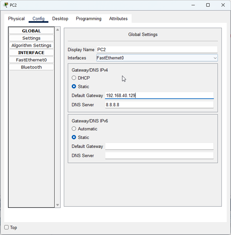
- We are not configuring DHCP in this project (that’ll be in a future one), so we are just statically configuring the IP addresses and default gateways for our hosts.
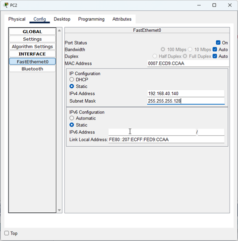
- We know what IP addresses to pick because of subnetting.
Now we need to determine how many hosts can fit in each of the two subnets. The formula for this is: 2^n where n = host bits. Remember, IPv4 addresses always have 32 bits. If we are using 25 of them for the network, that means we only have 7 for the host portion. 2^7 = 128. Each of our networks will have 128 possible addresses. However in IPv4, two addresses are always reserved for the network ID (first possible IP address) and the broadcast address (last possible address).
- IPv6 eliminates this limitation as it is more efficient.
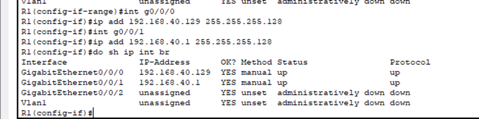
Therefore, we know the first LAN, the network for Accounts will have its IP range from 192.168.40.0-192.168.40.127. The range for the Delivery subnet will be 192.168.40.128-192.168.40.255. We decided to use the first usable IP address for each subnet, as their default gateway address. This is the address of the router’s interface directly connected to each LAN. Whenever a host in each LAN needs to send a packet outside of their LAN, it will go here.
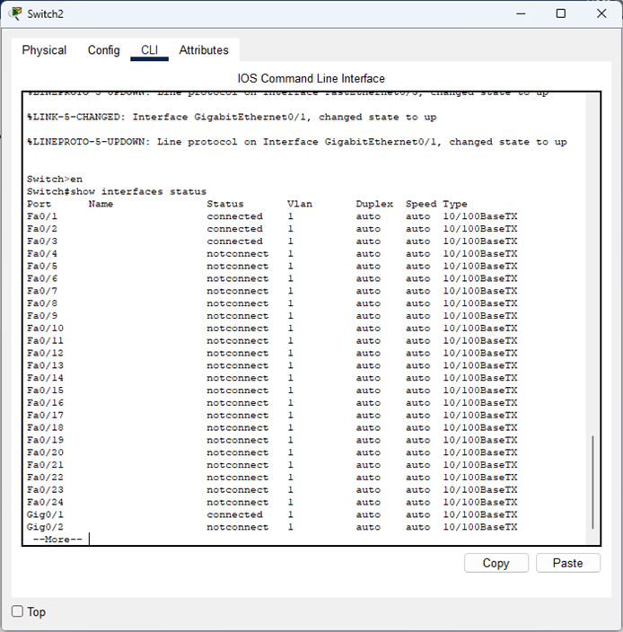
To determine which ports need configuring:
- Can use “show interfaces status” to verify active ports on the switch and use “show mac address-table” to find the MAC-Address associated with specific ports (traffic had to have traversed from these ports already however).
- Can use CDP or LLDP (multi-vendor environment) to find device neighbors. This can be a security risk however.
- Proper documentation/labelling and network diagrams.
- Physically plugging and unplugging cables to see network connectivity and link lights on devices (during maintenance windows).
- Using a cable tester to track a cable to find which port they’re connected to.
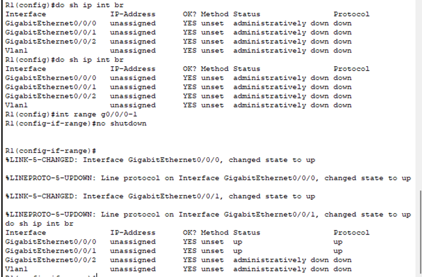
- Our router’s interfaces are administratively down. They also don’t have IP addresses assigned to them. How would our hosts communicate outside their LAN? Let’s fix that.
- Using bit values, we know that /25 is equivalent to .128 for the subnet mask.
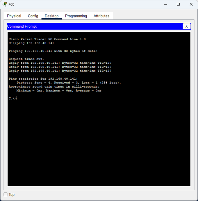
Lastly, we pinged PC2 in the DELIVERY subnet from PC0 in the ACCOUNTS subnet.
It was successful, so we know that both subnets can successfully communicate with each other.
- The reason the first ping failed is due to ARP (Address Resolution Protocol), in which the PC didn’t know the MAC address of the default gateway to be able to send its frame to it (this is a simplified version of it).
- Therefore, it sends a broadcast message (ARP Request) asking for the MAC address (Layer 2) of whoever has the IP of the default gateway. The switch floods this message out and the router interface sends an ARP Reply.
- The router then receives the original frame (actual ping), de-encapsulates the frame header and trailer to reveal the L3 packet. Using its routing table, it knows where to send the packet.
- During the ARP process, the switch populates its MAC address table with the source MAC address from each frame received.
